Quantcast
Channel: Kodeco | High quality programming tutorials: iOS, Android, Swift, Kotlin, Unity, and more
Viewing all 4398 articles
Browse latest View live

How to make a RESTful app with Siesta

$
0
0

How to make a RESTful app with Siesta

Fetching data over the network is one of the most common tasks in mobile apps. Therefore, it’s no surprise that networking libraries such as AFNetworking and Alamofire are some of the most popular libraries among iOS developers.

However, even with those libraries, you still must write and manage a lot repetitive code in an app simply to fetch and display data from the network. Some of these tasks include:

  • Managing duplicate requests.
  • Canceling requests that are no longer needed, such as when user exits a screen.
  • Fetching and processing data on background thread, and updating the UI on the main thread.
  • Parsing responses and converting them into model objects.
  • Showing and hiding loading indicators.
  • Displaying data when it arrives.

Siesta is a networking library that automates this work and reduces the complexity of your code involved in fetching and displaying data from the network.

By adopting a resource-centric approach, rather than a request-centric one, Siesta provides an app-wide observable model of a RESTful resource’s state.

Note: This tutorial assumes you understand the basics of making simple network requests using URLSession. If would like a refresher, check out our URLSession Tutorial: Getting Started tutorial.

Getting Started

In this tutorial, you’ll build Pizza Hunter, an app that lets users search for pizza restaurants around them.

Warning: you might feel hungry by the end of this tutorial!

Use the Download Materials button at the top or bottom of this tutorial to download the starter project.

Open the PizzaHunter.xcworkspace project, then build and run. You’ll see the following:

First run

The app already contains two view controllers:

  • RestaurantsListViewController: Displays a list of pizza restaurants at the selected location.
  • RestaurantDetailsViewController: Displays details about the selected restaurant.

Since the controllers aren’t connected to any data source, the app just shows a blank screen right now.

Note: Siesta 1.3 is the current version as of this writing and it has not been updated for Swift 4.1. You’ll get several deprecation warnings when you build the project. It’s safe to ignore these and your project will work normally.

Yelp API

You’ll be using the Yelp API to search for pizza restaurants in a city.

This is the request you’ll make to get a list of pizza restaurants:

GET https://api.yelp.com/v3/businesses/search

The JSON response to this request looks like this:

{
  "businesses": [
    {
      "id": "tonys-pizza-napoletana-san-francisco",
      "name": "Tony's Pizza Napoletana",
      "image_url": "https://s3-media2.fl.yelpcdn.com/bphoto/d8tM3JkgYW0roXBygLoSKg/o.jpg",
      "review_count": 3837,
      "rating": 4,
      ...
    },
    {
      "id": "golden-boy-pizza-san-francisco",
      "name": "Golden Boy Pizza",
      "image_url": "https://s3-media3.fl.yelpcdn.com/bphoto/FkqH-CWw5-PThWCF5NP2oQ/o.jpg",
      "review_count": 2706,
      "rating": 4.5,
      ...
    }
  ]
}

Making a Network Request in Siesta

The very first step is to create a class named YelpAPI.

Choose File ▸ New ▸ File from the menu, select Swift file and click Next. Name the file YelpAPI.swift, then Create. Replace the file’s contents with the following:

import Siesta

class YelpAPI {

}

This imports Siesta and creates the class stub for YelpAPI.

Siesta Service

You can now flesh out the code needed to make an API request. Inside the YelpAPI class, add the following:

static let sharedInstance = YelpAPI()

// 1
private let service = Service(baseURL: "https://api.yelp.com/v3", standardTransformers: [.text, .image, .json])

private init() {
  
  // 2
  LogCategory.enabled = [.network, .pipeline, .observers]
  
  service.configure("**") {
    
    // 3
    $0.headers["Authorization"] =
    "Bearer B6sOjKGis75zALWPa7d2dNiNzIefNbLGGoF75oANINOL80AUhB1DjzmaNzbpzF-b55X-nG2RUgSylwcr_UYZdAQNvimDsFqkkhmvzk6P8Qj0yXOQXmMWgTD_G7ksWnYx"
    
    // 4
    $0.expirationTime = 60 * 60 // 60s * 60m = 1 hour
  }
}

Here’s a step-by-step explanation of the above code:

  1. Each API service is represented by a Service class in Siesta. Since Pizza Hunter needs to talk to only one API — Yelp — you only need one Service class.
  2. Tell Siesta about the details you want it to log to the console.
  3. Yelp’s API requires clients to send their access token in every HTTP request header for authorization. This token is unique per Yelp account. For this tutorial, you may use this one or replace it with your own.
  4. Set the expirationTime to 1 hour, since restaurant review data won’t change very often.

Next, create a helper function in the YelpAPI class that returns a Resource object:

func restaurantList(for location: String) -> Resource {
  return service
    .resource("/businesses/search")
    .withParam("term", "pizza")
    .withParam("location", location)
}

This Resource object will fetch a list of pizza restaurants at the given location and make them available to any object that observes them. RestaurantListViewController will use this Resource to display the list of Restaurants in a UITableView. You’ll wire that up now so you can see Siesta in action.

Resource and ResourceObserver

Open RestaurantListViewController.swift and import Siesta at the top:

import Siesta

Next, inside the class, create an instance variable named restaurantListResource:

var restaurantListResource: Resource? {
  didSet {
    // 1
    oldValue?.removeObservers(ownedBy: self)

    // 2
    restaurantListResource?
      .addObserver(self)
      // 3
      .loadIfNeeded()
  }
}

When the restaurantListResource property is set, you do the following things:

  1. Remove any existing observers.
  2. Add RestaurantListViewController as an observer.
  3. Tell Siesta to load data for the resource if needed (based on the cache expiration timeout).

Since RestaurantListViewController is added as an observer, it also needs to conform to the ResourceObserver protocol. Add the following extension at the end of the file:

// MARK: - ResourceObserver
extension RestaurantListViewController: ResourceObserver {
  func resourceChanged(_ resource: Resource, event: ResourceEvent) {
    restaurants = resource.jsonDict["businesses"] as? [[String: Any]] ?? []
  }
}

Any object that conforms to the ResourceObserver protocol will get notifications about updates to the Resource.

These notifications will call resourceChanged(_:event:), passing the Resource object that was updated. You can inspect the event parameter to find out more about what was updated.

You can now put restaurantList(for:) that you wrote in YelpAPI class to use.

currentLocation, the property on RestaurantListViewController, gets updated when user selects a new location from the drop down.

Whenever that happens, you should also update the restaurantListResource with the newly selected location. To do so, replace the existing currentLocation declaration with the following:

var currentLocation: String! {
  didSet {
    restaurantListResource = YelpAPI.sharedInstance.restaurantList(for: currentLocation)
  }
}

If you run the app now, Siesta will log the following output in your console:

Siesta:network        │ GET https://api.yelp.com/v3/businesses/search?location=Atlanta&term=pizza
Siesta:observers      │ Resource(…/businesses/search?location=Atlanta&term=pizza)[L] sending requested event to 1 observer
Siesta:observers      │   ↳ requested → <PizzaHunter.RestaurantListViewController: 0x7ff8bc4087f0>
Siesta:network        │ Response:  200 ← GET https://api.yelp.com/v3/businesses/search?location=Atlanta&term=pizza
Siesta:pipeline       │ [thread ᎰᏮᏫᎰ]  ├╴Transformer ⟨*/json */*+json⟩ Data → JSONConvertible [transformErrors: true] matches content type "application/json"
Siesta:pipeline       │ [thread ᎰᏮᏫᎰ]  ├╴Applied transformer: Data → JSONConvertible [transformErrors: true] 
Siesta:pipeline       │ [thread ᎰᏮᏫᎰ]  │ ↳ success: { businesses = ( { categories = ( { alias = pizza; title = Pizza; } ); coordinat…
Siesta:pipeline       │ [thread ᎰᏮᏫᎰ]  └╴Response after pipeline: success: { businesses = ( { categories = ( { alias = pizza; title = Pizza; } ); coordinat…
Siesta:observers      │ Resource(…/businesses/search?location=Atlanta&term=pizza)[D] sending newData(network) event to 1 observer
Siesta:observers      │   ↳ newData(network) → <PizzaHunter.RestaurantListViewController: 0x7ff8bc4087f0>

These logs give you some insight into what tasks Siesta is performing:

  • Kicks off the GET request to search for pizza places in Atlanta.
  • Notifies the observer i.e. RestaurantListViewController about the request.
  • Gets the results with response code 200.
  • Converts raw data into JSON.
  • Sends the JSON to RestaurantListViewController.

You can set a breakpoint in resourceChanged(_:event:) in RestaurantListViewController and type

po resource.jsonDict["businesses"]

in the console to see the JSON response. You’ll have to skip the breakpoint once as resourceChanged is called when the observer is first added, but before any data has come in.

To display this restaurant list in your tableView, you need to reload the tableView when restaurants property is set. In RestaurantListViewController, replace the restaurants property with:

private var restaurants: [[String: Any]] = [] {
  didSet {
    tableView.reloadData()
  }
}

Build and run your app to see it in action:

Hurray! You just found yourself some delicious pizza. :]

Adding the Spinner

There isn’t a loading indicator to inform the user that the restaurant list for a location is being downloaded.

Siesta comes with ResourceStatusOverlay, a built-in spinner UI that automatically displays when your app is loading data from the network.

To use ResourceStatusOverlay, first add it as an instance variable of RestaurantListViewController:

private var statusOverlay = ResourceStatusOverlay()

Now add it to the view hierarchy by adding the following code at the bottom of viewDidLoad():

statusOverlay.embed(in: self)

The spinner must be placed correctly every time the view lays out its subviews. To ensure this happens, add the following method under viewDidLoad():

override func viewDidLayoutSubviews() {
  super.viewDidLayoutSubviews()
  statusOverlay.positionToCoverParent()
}

Finally, you can make Siesta automatically show and hide statusOverlay by adding it as an observer of restaurantListResource. To do so, add the following line between .addObserver(self) and .loadIfNeeded() in the restaurantListResource‘s didSet:

.addObserver(statusOverlay, owner: self)

Build and run to see your beautiful spinner in action:

You’ll also notice that selecting the same city a second time shows the results almost instantly. This is because the first time the restaurant list for a city loads, it’s fetched from the API. But Siesta caches the responses and returns responses for subsequent requests for the same city from its in-memory cache:

Siesta Transformers

For any non-trivial app, it’s better to represent the response from an API with well-defined object models instead of untyped dictionaries and arrays. Siesta provides hooks that make it easy to transform a raw JSON response into an object model.

Restaurant Model

PizzaHunter stores the id, name and url for each Restaurant. Right now, it does this by manually picking that data from the JSON returned by Yelp. Improve on this by making Restaurant conform to Codable so that you get clean, type-safe JSON decoding for free.

To do this, open Restaurant.swift and replace the struct with the following:

struct Restaurant: Codable {
  let id: String
  let name: String
  let imageUrl: String

  enum CodingKeys: String, CodingKey {
    case id
    case name
    case imageUrl = "image_url"
  }
}
Note: If you need a refresher on Codable and CodingKey, check out our Encoding, Decoding and Serialization in Swift 4 tutorial.

If you look back at the JSON you get from the API, your list of restaurants is wrapped inside a dictionary named businesses:

{
  "businesses": [
    {
      "id": "tonys-pizza-napoletana-san-francisco",
      "name": "Tony's Pizza Napoletana",
      "image_url": "https://s3-media2.fl.yelpcdn.com/bphoto/d8tM3JkgYW0roXBygLoSKg/o.jpg",
      "review_count": 3837,
      "rating": 4,
      ...
    },

You’ll need a struct to unwrap the API response that contains a list of businesses. Add this to the bottom of Restaurant.swift:

struct SearchResults<T: Decodable>: Decodable {
  let businesses: [T]
}

Model Mapping

Open YelpAPI.swift and add the following code at the end of init():

let jsonDecoder = JSONDecoder()

service.configureTransformer("/businesses/search") {
  try jsonDecoder.decode(SearchResults<Restaurant>.self, from: $0.content).businesses
}

This transformer will take any resource that hits the /business/search endpoint of the API and pass the response JSON to SearchResults‘s initializer. This means you can create a Resource that returns a list of Restaurant instances.

Another small but crucial step is to remove .json from the standard transformers of your Service. Replace the service property with the following:

private let service = Service(baseURL: "https://api.yelp.com/v3", standardTransformers: [.text, .image])

This is how Siesta knows to not apply its standard transformer to any response that is of type JSON, but instead use the custom transformer that you have provided.

RestaurantListViewController

Now update RestaurantListViewController so that it can handle object models from Siesta, instead of raw JSON.

Open RestaurantListViewController.swift and update restaurants to be an array of type Restaurant:

private var restaurants: [Restaurant] = [] {
  didSet {
    tableView.reloadData()
  }
}

And update tableView(_:cellForRowAt:) to use the Restaurant model. Do this by replacing:

cell.nameLabel.text = restaurant["name"] as? String
cell.iconImageView.imageURL = restaurant["image_url"] as? String

with

cell.nameLabel.text = restaurant.name
cell.iconImageView.imageURL = restaurant.imageUrl

Finally, update the implementation of resourceChanged(_:event:) to extract a typed model from the resource instead of a JSON dictionary:

// MARK: - ResourceObserver
extension RestaurantListViewController: ResourceObserver {
  func resourceChanged(_ resource: Resource, event: ResourceEvent) {
    restaurants = resource.typedContent() ?? []
  }
}

typedContent() is a convenience method that returns a type-cast value for the latest result for the Resource if available or nil if it’s not.

Build and run, and you’ll see nothing has changed. However, your code is a lot more robust and safe due to the strong typing!

Building the Restaurant Details Screen

If you’ve followed along until now, the next part should be a breeze. You’ll follow similar steps to fetch details for a restaurant and display it in RestaurantDetailsViewController.

RestaurantDetails Model

First, you need the RestaurantDetails and Location structs to be codable so that you can use strongly-typed models going forward.

Open RestaurantDetails.swift and make both RestaurantDetails and Location conform to Codable like so:

struct RestaurantDetails: Codable {
struct Location: Codable {

Next, implement the following CodingKeys for RestaurantDetails just like you did with Restaurant earlier. Add the following inside RestaurantDetails:

enum CodingKeys: String, CodingKey {
  case name
  case imageUrl = "image_url"
  case rating
  case reviewCount = "review_count"
  case price
  case displayPhone = "display_phone"
  case photos
  case location
}

And, finally, add the following CodingKeys to Location:

enum CodingKeys: String, CodingKey {
  case displayAddress = "display_address"
}

Model Mapping

In YelpAPI‘s init(), you can reuse the previously created jsonDecoder to add the transformer that tells Siesta to convert restaurant details JSON to RestaurantDetails. To do this, open YelpAPI.swift and add the following line above the previous call to service.configureTransformer:

service.configureTransformer("/businesses/*") {
  try jsonDecoder.decode(RestaurantDetails.self, from: $0.content)
}

Also, add another helper function to the YelpAPI class, that creates a Resource object to query restaurant details:

func restaurantDetails(_ id: String) -> Resource {
  return service
    .resource("/businesses")
    .child(id)
}

So far, so good. You’re now ready to move on to the view controller to see your models in action.

Setting up Siesta in RestaurantDetailsViewController

RestaurantDetailsViewController is the view controller displayed whenever the user taps on a restaurant in the list. Open RestaurantDetailsViewController.swift and add the following code below restaurantDetail:

// 1
private var statusOverlay = ResourceStatusOverlay()

override func viewDidLoad() {
  super.viewDidLoad()

  // 2
  YelpAPI.sharedInstance.restaurantDetails(restaurantId)
    .addObserver(self)
    .addObserver(statusOverlay, owner: self)
    .loadIfNeeded()

  // 3
  statusOverlay.embed(in: self)
}

override func viewDidLayoutSubviews() {
  super.viewDidLayoutSubviews()
  // 4
  statusOverlay.positionToCoverParent()
}
  1. Like before, you setup a status overlay which is shown when content is being fetched.
  2. Next, you request restaurant details for a given restaurantId when the view loads. You also add self and the spinner as observers to the network request so you can act when a response is returned.
  3. Like before, you add the spinner to the view controller.
  4. Finally, you make sure the spinner is placed correctly on the screen after any layout updates.

Handling the Navigation to RestaurantDetailsViewController

Finally, you may have noticed that the app doesn’t yet navigate to a screen that shows the details of a restaurant. To do so, open RestaurantDetailsViewController.swift and locate the following extension:

extension RestaurantListViewController: UITableViewDelegate {

Next, add the following delegate method inside of the extension:

func tableView(_ tableView: UITableView, didSelectRowAt indexPath: IndexPath) {
  guard indexPath.row <= restaurants.count else {
    return
  }
  
  let detailsViewController = UIStoryboard(name: "Main", bundle: nil)
    .instantiateViewController(withIdentifier: "RestaurantDetailsViewController") 
      as! RestaurantDetailsViewController
  detailsViewController.restaurantId = restaurants[indexPath.row].id
  navigationController?.pushViewController(detailsViewController, animated: true)
  tableView.deselectRow(at: indexPath, animated: true)
}

Here you simply set up the details view controller, pass in restaurantId for the selected restaurant, and push it on the navigation stack.

Build and run the app. You can now tap on a restaurant that's listed. Tada!

If you swipe back and tap on the same restaurant, you'll see the restaurant details load instantly. This is another example of Siesta's local caching behavior delivering a great user experience:

That’s it! You've built a restaurant search app using Yelp's API and the Siesta framework.

Where to Go From Here?

You can download the completed version of the project using the Download Materials button at the top or bottom of this tutorial.

Siesta's GitHub page is an excellent resource if you'd like to read their documentation.

To dig deeper into Siesta, check out the following resources:

I hope you found this tutorial useful. Please share any comments or questions in the forum discussion below!

The post How to make a RESTful app with Siesta appeared first on Ray Wenderlich.


Introducing the Game On Book Launch Event!

$
0
0

We’re excited to introduce an amazing lineup of new and updated books as part of our Game On book launch!

We have four new and updated books as part of our Game On event:

  • ARKit by Tutorials: The easiest and fastest way to get started building augmented reality apps in ARKit! You’ll build five great-looking, immersive apps in this book: tabletop poker dice, an immersive sci-fi portal, 3D face masking, location-based ad content, and a monster truck sim!
  • Metal by Tutorials: Build your own low-level 3D game engine as you learn how to program for Metal, Apple’s framework for programming on the GPU. You’ll start at the beginning, learn all about rendering, lighting, textures, maps, post-processing, procedural generation, multipass and deferred rendering, and tie it all together at the end by integrating your engine with SpriteKit and SceneKit!
  • Beat ’Em Up Game Starter Kit – Unity: The classic beat ’em up starter kit is back — for Unity! Create your own side-scrolling beat ’em up game in the style of such arcade classics as Double Dragon, Teenage Mutant Ninja Turtles, Golden Axe and Streets of Rage. This starter kit equips you with all tools, art and instructions you’ll need to create your own addictive mobile game for Android and iOS.
  • Unity Games by Tutorials: We’re updating our classic text in building 2D and 3D games in Unity for Unity 2018.1. In this book, you’ll create four complete games from scratch: A twin-stick shooter, a first-person shooter, a tower defense game (with VR support!), and a 2D platfomer. By the end of this book, you’ll be ready to make your own games for Windows, macOS, iOS, and more!

To help celebrate these books, and help you get your game on, we’re featuring some special launch pricing of these books, sharing free chapters from the books to give you a taste of what’s inside, and we’ll even have a giveaway where a few lucky readers can win themselves a copy of the books we’re featuring in our Game On event!

Here’s a quick overview of what’s in each book:

ARKit by Tutorials

Learn how to use Apple’s augmented reality framework, ARKit, to build five immersive, great-looking AR apps!

ARKit is Apple’s mobile AR development framework. With it, you can create an immersive, engaging experience, mixing virtual 2D and 3D content with the live camera feed of the world around you.

What sets ARKit apart from other AR frameworks, such as Vuforia, is that ARKit performs markerless tracking. ARKit instantly transforms any Apple device with an A9 or higher processor into a markerless AR-capable device. At this very moment, millions of Apple users already have a sophisticated AR device right in their pockets!

If you’ve worked with any of Apple’s other frameworks, you’re probably expecting that it will take a long time to get things working. But with ARKit, it only takes a few lines of code — ARKit does most of the the heavy lifting for you, so you can focus on what’s important: creating an immersive and engaging AR experience.

In this book, you’ll build five immersive, great-looking AR apps:

  • Tabletop Poker Dice
  • Immersive Sci-Fi Portal
  • 3D Face Masking
  • Location-Based Content
  • Monster Truck Sim

Create your own personal portal in augmented reality!

By the end of the book, you’ll have a ton of great experience working inside the ARKit framework, including how to work with 3D objects and textures, how to add game physics, detect placeholders, how to work with face-based AR, how to work with blend shapes, record your experience with ReplayKit, and more!

We’ll be releasing three sample chapters from this book this week: keep watching the site for details!

About the Authors

Chris Language is a seasoned coder with 20+ years of experience, and the author of 3D Apple Games by Tutorials. He has fond memories of his childhood and his Commodore 64; more recently he started adding more good memories of life with all his Apple devices. By day, he fights for survival in the corporate jungle of Johannesburg, South Africa. By night he fights demons, dragons and zombies! For relaxation, he codes. You can find him on Twitter @ChrisLanguage.

Namrata Bandekar is a Software Engineer focusing on native iOS and Android development. When she’s not developing apps, she enjoys spending her time travelling the world with her husband, SCUBA diving and hiking with her dog. Say hi to Namrata on Twitter: @NamrataCodes.

Antonio Bello is still in love with software development, even after several decades spent writing code. Besides writing code that works and can be read by humans, his primary focus is learning; he’s actually obsessed by trying a bit of everything. When he’s not working, he’s probably sleeping (someone says he works too much), but from time to time he might be playing drums or composing music.

Tammy Coron is an independent creative professional and the host of Roundabout: Creative Chaos. She’s also the founder of Just Write Code. Find out more at tammycoron.com.

Metal by Tutorials

Build your own low-level game engine in Metal!

This book will introduce you to graphics programming in Metal — Apple’s framework for programming on the GPU. You’ll build your own game engine in Metal where you can create 3D scenes and build your own 3D games.

Metal is a unified application programming interface (API) for the graphics processing unit, or GPU. It’s unified because it applies to both 3D graphics and data-parallel computation paradigms. Metal is a low-level API because it provides programmers near-direct access to the GPU. Finally, Metal is a low-overhead API because it reduces the central processing unit (CPU) cost by multi-threading and pre-compiling of resources.

But beyond the technical definition, Metal is the most appropriate way to use the GPU’s parallel processing power to visualize data or solve numerical challenges. It’s also tailored to be used for machine learning, image/video processing or, as this book describes, graphics rendering.

Learn the details behind 3D rendering with Metal!

This book will introduce you to low-level graphics programming in Metal — Apple’s framework for programming on the graphics processing unit (GPU). As you progress through this book, you’ll learn many of the fundamentals that go into making a game engine and gradually put together your own engine. Once your game engine is complete, you’ll be able to put together 3D scenes and program your own simple 3D games. Because you’ll have built your 3D game engine from scratch, you’ll be able to customize every aspect of what you see on your screen.

This book is for intermediate Swift developers interested in learning 3D graphics or gaining a deeper understanding of how game engines work.

This book is currently in early access release with four full chapters available to get you started with Metal. When you purchase the digital edition, you’ll get advance access to the book while it’s in development, and you’ll get a free update to the complete digital edition of the book when it’s released! Estimated final release date is Fall, 2018.

We’ll be releasing a free sample chapter from this book this week on the site: keep watching for details!

About the Authors

Caroline Begbie is an indie iOS developer. When she’s not developing, she’s playing around with 2D and 3D animation software, or learning Arduino and electronics. She has previously taught the elderly how to use their computers, done marionette shows for pre-schools, and created accounting and stock control systems for mining companies.

Marius Horga is an iOS developer and Metal API blogger. He is also a computer scientist. He has more than a decade of experience with systems, support, integration and development. You can often see him on Twitter talking about Metal, GPGPU, games and 3D graphics. When he’s away from computers, he enjoys music, biking or stargazing.

Beat ’Em Up Game Starter Kit

Create your own side-scrolling beat ’em up game in the style of such arcade classics as Double Dragon, Teenage Mutant Ninja Turtles, Golden Axe and Streets of Rage!

This starter kit equips you with all tools, art and instructions you’ll need to create your own addictive mobile game for Android and iOS.

What could possibly be a more amusing way to burn time than slaughtering a horde of bad guys with trusty right and left hooks? Creating your very own beat ‘em up game, of course!

Beat ‘em up games have been around since the inception of 8-bit games and experienced their glory days when early console gaming and arcade gaming were all the rage — long before the world turned to pixels in the early part of the 21st century.

In the Unity version of this popular book, we’ll walk you through building a complete beat ’em up game on Unity.

With Unity’s great suite of 2D tools, it’s easy to build a game once and make it available to multiple platforms. The dark days of building for one platform, then painstakingly building your ingenious game on another engine for a different platform are over!

Get your retro on and build a classic beat ’em up game in Unity!

More than a book, this starter kit equips you with the tools, assets, fresh starter projects for each chapter, and step-by-step instructions to create an addictive beat ‘em up game for Android and iOS.

Each chapter builds on the last. You build out features one at a time, allowing you to learn at a steady, logical, and fun pace. Components were designed with reusability in mind so you can easily customize the resulting game.

This starter kit is for beginner to intermediate developers who have at least poked around Unity, perhaps even built a game, but need guidance around how to create a beat ‘em up game.

We’ll be releasing a free sample from one of the chapters of this book on the site next Monday, June 5, as a taste of what’s in this book.

And even more great news: if you’d already purchased our old Beat ’Em Up Game Starter Kit, SpriteKit edition, you quality for a 50% discount off of the regular price of the new Unity version of the book! To claim your special upgrade price, simply email support@razeware.com with your raywenderlich.com account name or email, and we’ll get you sorted.

About the Author

Jonathan Simbahan is a Philippines-based game programmer with a curious mind on a quest to make enjoyable games. Outside of game development, he finds simple joys in his numerous hobbies which are usually food-related.

Unity Games by Tutorials

Learn how to make games in Unity: a professional game engine used to create games like City Skylines, Hearthstone, the Long Dark, and more.

In this book, you’ll create four complete games from scratch:

  • A twin-stick shooter
  • A first-person shooter
  • A tower defense game (with VR support!)
  • A 2D platfomer

By the end of this book, you’ll be ready to make your own games for Windows, macOS, iOS, and more!

This book is for complete beginners to Unity, or for those who’d like to bring their Unity skills to a professional level. The book assumes you have some prior programming experience (in a language of your choice).

If you are a complete beginner to programming, we recommend you learn some basic programming skills first. A great way to do that is to watch our free Beginning C# with Unity series, which will get you familiar with programming in the context of Unity.

The games in the book are made with C#. If you have prior programming experience but are new to C#, don’t worry – the book includes an appendix to give you a crash course on C# syntax.

We’ll be releasing some free chapters from this book next week. Stay tuned to the site for details!

This book will be updated for Unity 2018.1 on June 6, 2018. If you already own this book, or buy it before June 6, 2018, you’ll receive a free update to the Unity 2018.1 version of the book when it’s released!

About the Authors

MikeMike Berg Mike Berg is a full-time game artist who is fortunate enough to work with many indie game developers from all over the world. When he’s not manipulating pixel colors, he loves to eat good food, spend time with his family, play games and be happy. You can check out his work at www.weheartgames.com.

SeanSean Duffy is a software engineer by day, and hobbyist game and tools developer by night. He loves working with Unity, and is also a Unity Asset Store developer with a special focus on 2D tools to help other game developers. Some of Sean’s more popular Unity Assets include his 2D Shooter Bullet and Weapon System and 2D Homing Missiles assets. You can find Sean on Twitter at @shogan85.

BrianBrian Moakley produces video tutorials on iOS, Unity, and various other topics for raywenderlich.com. When not writing or coding, Brian enjoys story driven first person shooters, reading genre fiction, and epic board game sessions with friends.

EricEric Van de Kerckhove leads the Unity team at raywenderlich.com. He is a Belgian hobbyist game dev and has been so for more than 15 years.
He has made a fair share of games over the years, mostly free ones for fun and as learning experiences. Eric leads the Unity team at raywenderlich.com.”

AnthonyAnthony Uccello Anthony is a software consultant who spends his night hours coding away making games in Unity. He is married and has 3 dogs and 3 cats.

Game On Book Launch Discounts

To celebrate the launch of these great books, we’re offering a limited-time launch discount pricing of $44.99 each! That’s a savings of $10 over the regular price!

All books are available in both PDF and EPUB formats, and come with all the source code for the book, including starter and final projects to help you on your learning path.

But don’t wait: these discounts are only good until the end of Friday, June 8. Get your start in game development and snag some sweet savings while you’re at it!

Game On Book Giveaway

We’re giving away three copies of each of the books in our Game On book launch event: ARKit by Tutorials, Metal by Tutorials, Beat ’Em Up Game Starter Kit, and Unity Games by Tutorials, to a few lucky readers.

To enter the giveaway, simply leave a comment below and answer the following question:

What book are you most excited about in our Game On book launch event?

We’ll select three winners at random for each book in our Game On lineup who leave a comment below before Friday, June 8. Get your entries in early — there are twelve chances to win, so your odds are really good on this one!

Where to Go From Here?

To recap, here’s the schedule of events for the Game On Book Launch:

  • May 29: ARKit by Tutorials, Metal by Tutorials, Beat ’Em Up Game Starter Kit Unity books released!
  • May 30: Metal free chapter released
  • May 31: ARKit free chapter #1 and #2 released
  • June 1: ARKit free chapter #3 released
  • June 5: Beat ’Em Up Game Starter Kit free chapter released
  • June 6: Unity Games by Tutorials updated to Unity 2018.1
  • June 8: Giveaway and last day for discount!

If you’re looking to get started in Unity game development, or want to dig deeper into frameworks like ARKit and Metal, there’s no better way to boost your game building chops than through the books featured in our Game On book launch.

And don’t forget about the limited-time launch discount pricing of all four of these books — only available until the end of Friday, June 8. Don’t miss out!

We truly appreciate the support from all of our readers; you help make everything we do here at raywenderlich.com possible. Thanks for your support — and don’t forget to leave a comment below to enter the giveaway!

The post Introducing the Game On Book Launch Event! appeared first on Ray Wenderlich.

Drawing in iOS – Part 2: Core Graphics

$
0
0

Part two of our new course, Drawing in iOS, is available today!
If you’re familiar with the basics of creating iOS user interfaces, but want to take your skills up a notch, this course is for you.

In part two, you’ll tap into the power of Core Graphics to create three more controls. You’ll learn how to draw with Core Graphics, create reusable images, apply transforms, use Core Graphics gradients, and more!

Take a look at what’s inside:

Part 2: Core Graphics

  1. Introduction: Let’s review what you’ll be learning in this section, and find out about the three controls you’ll design.
  2. Core Graphics Drawing: So how do you draw into a view? Find out how to draw a cupcake.
  3. Challenge: Customize a Button: Complete your custom button in this hands-on challenge.
  4. Images and Contexts: Find out what a context is and how to create a reusable image.
  5. Transforms: Learn how to move your canvas before painting into it by using transforms.
  6. Challenge: Draw Clock Numbers: Put your transform knowledge to use by drawing numbers into your timer.
  7. Core Graphics Gradients: More powerful than CAGradientLayer – learn how to use Core Graphics gradients in a graph background.
  8. Challenge: Complete a graph: Complete a graph from dynamic data by “drawing” on everything you’ve learned in this hands-on challenge.
  9. Conclusion: Let’s review what you learned throughout the course and discuss where to go next.

Where To Go From Here?

Want to check out the course? You can watch the Introduction for this part and Core Graphics Drawing for free!

The rest of the course is for raywenderlich.com subscribers only. Here’s how you can get access:

  • If you are a raywenderlich.com subscriber: The entire course is now ready to watch! You can check out the course here.
  • If you are not a subscriber yet: What are you waiting for? Subscribe now to get access to our new Drawing in iOS course and our entire catalog of over 500 videos.

Stay tuned for more new and updated courses to come. I hope you enjoy the course! :]

The post Drawing in iOS – Part 2: Core Graphics appeared first on Ray Wenderlich.

Geofencing with Core Location: Getting Started

$
0
0
Update note: Andy Pereira updated this tutorial for Xcode 9.3 and Swift 4.1.
geofencing

Let’s get geofencing!

Geofencing notifies your app when its device enters or leaves geographical regions you set up. It lets you make cool apps that can trigger a notification whenever you leave home, or greet users with the latest and greatest deals whenever favorite shops are nearby. In this geofencing tutorial, you’ll learn how to use region monitoring in iOS with Swift – using the Region Monitoring API from Core Location.

In particular, you’ll create a location-based reminder app called Geotify that will let the user create reminders and associate them with real-world locations. Time to get started!

Getting Started

Use the Download Materials at the top or bottom of this tutorial to download the starter project. It provides a simple user interface for adding/removing annotation items to/from a map view. Each annotation item represents a reminder with a location, or as I like to call it, a geotification. :]

Build and run the project, and you’ll see an empty map view.

geofencing

Tap the + button on the navigation bar to add a new geotification. The app will present a separate view, allowing you to set up various properties for your geotification.

For this tutorial, you will add a pin on Apple’s new headquarters in Cupertino. If you don’t know where it is, open this Google map and use it to hunt the right spot. Be sure to zoom in to make the pin nice and accurate!

Note: To pinch to zoom on the simulator, hold down option, then hold shift temporarily to move the pinch center, then release shift and click-drag to pinch.

geofencing

The Radius represents the distance in meters from the specified location, at which iOS will trigger the notification. The Note can be any message you wish to display during the notification. The app also lets the user specify whether it should trigger the reminder upon either entry or exit of the defined circular geofence, via the segmented control at the top.

Enter 1000 for the radius value and Say Hi to Tim! for the note, and leave it as Upon Entry for your first geotification.

Click Add once you’re satisfied with all the values. You’ll see your geotification appear as a new annotation pin on the map view, with a circle around it denoting the defined geofence:

Tap the pin and you’ll reveal the geotification’s details, such as the reminder note and the event type you specified earlier. Don’t tap the little cross unless you want to delete the geotification!

Feel free to add or remove as many geotifications as you want. Since the app uses UserDefaults as a persistence store, the list of geotifications will persist between relaunches.

Setting Up Core Location and Permissions

At this point, any geotifications you’ve added to the map view are only for visualization. You’ll fix this by taking each geotification and registering its associated geofence with Core Location for monitoring.

Before any geofence monitoring can happen, though, you need to set up a CLLocationManager instance and request the appropriate permissions.

Open GeotificationsViewController.swift and declare a constant instance of a CLLocationManager. Add the following after var geotifications: [Geotification] = []:

let locationManager = CLLocationManager()

Next, replace viewDidLoad() with the following code:

override func viewDidLoad() {
  super.viewDidLoad()
  // 1
  locationManager.delegate = self
  // 2
  locationManager.requestAlwaysAuthorization()
  // 3
  loadAllGeotifications()
}

Here’s an overview of this method step by step:

  1. You set the view controller as the delegate of the locationManager instance so that the view controller receives the relevant delegate method calls.
  2. You call requestAlwaysAuthorization(), which displays a prompt to the user requesting authorization to use location services Always. Apps with geofencing capabilities require Always authorization since they must monitor geofences even when the app isn’t running. Info.plist already contains the message to show the user under the key NSLocationAlwaysAndWhenInUseUsageDescription. Since iOS 11, all apps that request Always also allow the user to select When In Use. Info.plist also contains a message for NSLocationWhenInUseUsageDescription. It’s important to explain to your users as simply as possible why they need to have Always selected.
  3. You call loadAllGeotifications(), which deserializes the list of geotifications previously saved to UserDefaults and loads them into the local geotifications array. The method also adds the geotifications as annotations on the map view.

When the app prompts the user for authorization, it will show NSLocationAlwaysAndWhenInUseUsageDescription, a user-friendly explanation of why the app requires access to the user’s location. This key is mandatory when you request authorization for location services. If it’s missing, the system will ignore the request and prevent location services from starting altogether.

Build and run the project; you’ll see a user prompt with the aforementioned description that’s been set:

You’ve set up your app to request the required permission. Great! Click or tap Allow to ensure the location manager will receive delegate callbacks at the appropriate times.

Before you proceed to implement the geofencing, there’s a small issue you have to resolve: the user’s current location isn’t showing up on the map view! By default, the map view disables this feature and, as a result, the zoom button on the top-left of the navigation bar doesn’t work.

Fortunately, the fix is not difficult — you’ll simply enable the current location only after the user authorizes the app.

In GeotificationsViewController.swift, add the following delegate method to the CLLocationManagerDelegate extension:

func locationManager(_ manager: CLLocationManager, didChangeAuthorization status: CLAuthorizationStatus) {
  mapView.showsUserLocation = (status == .authorizedAlways)
}

The location manager calls locationManager(_:didChangeAuthorizationStatus:) whenever the authorization status changes. If the user has already granted the app permission to use Location Services, the location manager calls this method after you’ve initialized the location manager and set its delegate.

That makes this method an ideal place to check for app authorization. If it is, you enable the map view to show the user’s current location.

Build and run the app. If you’re running it on a device, you’ll see the location marker appear on the main map view. If you’re running on the simulator, click Debug ▸ Location ▸ Apple in the menu to see the location marker:

In addition, the zoom button on the navigation bar now works. :]

Registering Your Geofences

With the location manager properly configured, you must now allow your app to register user geofences for monitoring.

Your app stores the user geofence information within your custom Geotification model. However, to monitor geofences, Core Location requires you to represent each one as a CLCircularRegion instance. To handle this requirement, you’ll create a helper method that returns a CLCircularRegion from a given Geotification object.

Open GeotificationsViewController.swift and add the following method to the main body:

func region(with geotification: Geotification) -> CLCircularRegion {
  // 1
  let region = CLCircularRegion(center: geotification.coordinate, 
    radius: geotification.radius, 
    identifier: geotification.identifier)
  // 2
  region.notifyOnEntry = (geotification.eventType == .onEntry)
  region.notifyOnExit = !region.notifyOnEntry
  return region
}

Here’s what the above method does:

  1. You initialize a CLCircularRegion with the location of the geofence, the radius of the geofence and an identifier that allows iOS to distinguish between the registered geofences of a given app. The initialization is rather straightforward as the Geotification model already contains the required properties.
  2. CLCircularRegion also has two boolean properties: notifyOnEntry and notifyOnExit. These flags specify whether to trigger geofence events when the device enters or leaves the defined geofence, respectively. Since you’re designing your app to allow only one notification type per geofence, you set one of the flags to true and the other to false based on the eventType value stored in the Geotification object.

Next, you need a method to start monitoring a given geotification whenever the user adds one.

Add the following method to the body of GeotificationsViewController:

func startMonitoring(geotification: Geotification) {
  // 1
  if !CLLocationManager.isMonitoringAvailable(for: CLCircularRegion.self) {
    showAlert(withTitle:"Error", message: "Geofencing is not supported on this device!")
    return
  }
  // 2
  if CLLocationManager.authorizationStatus() != .authorizedAlways {
    let message = """
      Your geotification is saved but will only be activated once you grant 
      Geotify permission to access the device location.
      """
    showAlert(withTitle:"Warning", message: message)
  }
  // 3
  let fenceRegion = region(with: geotification)
  // 4
  locationManager.startMonitoring(for: fenceRegion)
}

Here’s an overview of this method step by step:

  1. isMonitoringAvailableForClass(_:) determines if the device has the required hardware to support the monitoring of geofences. If monitoring is unavailable, you bail out entirely and alert the user accordingly. showAlert(withTitle:message:) is a helper function in Utilities.swift that takes a title and message and displays an alert view.
  2. Next, you check the authorization status to ensure the user has granted the app the required permission to use Location Services. If the user hasn’t granted permission, the app won’t receive any geofence-related notifications. However, in this case, you’ll still allow the user to save the geofence, since Core Location doesn’t require permission to register geofences. When the user subsequently grants authorization to the app, monitoring for those geofences will begin automatically.
  3. You create a CLCircularRegion instance from the given geotification using the helper method you defined earlier.
  4. Finally, you register the CLCircularRegion instance with Core Location for monitoring via the CLLocationManager.

With your start method done, you also need a method to stop monitoring a given geotification when the user removes it from the app.

In GeotificationsViewController.swift, add the following method below startMonitoring(geotificiation:):

func stopMonitoring(geotification: Geotification) {
  for region in locationManager.monitoredRegions {
    guard let circularRegion = region as? CLCircularRegion, 
      circularRegion.identifier == geotification.identifier else { continue }
    locationManager.stopMonitoring(for: circularRegion)
  }
}

The method simply instructs the locationManager to stop monitoring the CLCircularRegion associated with the given geotification.

Now that you have both the start and stop methods complete, you’ll use them whenever you add or remove a geotification. You’ll begin with the adding part.

First, take a look at addGeotificationViewController(_:didAddCoordinate:radius:identifier:note:eventType:) in GeotificationsViewController.swift.

This is the delegate method invoked by AddGeotificationViewController upon creating a geotification. It’s responsible for creating a new Geotification object and updating both the map view and the geotifications list accordingly. Finally, it calls saveAllGeotifications(), which takes the newly-updated geotifications list and persists it via UserDefaults.

Now, replace addGeotificationViewController(_:didAddCoordinate:radius:identifier:note:eventType:) with the following:

func addGeotificationViewController(
  _ controller: AddGeotificationViewController, didAddCoordinate coordinate: CLLocationCoordinate2D, 
  radius: Double, identifier: String, note: String, eventType: Geotification.EventType
) {
  controller.dismiss(animated: true, completion: nil)
  // 1
  let clampedRadius = min(radius, locationManager.maximumRegionMonitoringDistance)
  let geotification = Geotification(coordinate: coordinate, radius: clampedRadius, 
    identifier: identifier, note: note, eventType: eventType)
  add(geotification)
  // 2
  startMonitoring(geotification: geotification)
  saveAllGeotifications()
}

You’ve made two key changes to the code:

  1. You ensure the value of the radius doesn’t exceed the maximumRegionMonitoringDistance property of locationManager, which defines the largest radius, in meters, for a geofence. This is important as any value that exceeds this maximum will cause monitoring to fail.
  2. You add a call to startMonitoring(geotification:) to register the newly-added geotification with Core Location for monitoring.

At this point, the app is fully capable of registering new geofences for monitoring. There is, however, a limitation: As geofences are a shared system resource, Core Location restricts the number of registered geofences to a maximum of 20 per app.

While there are workarounds to this limitation (See Where to Go From Here? at the bottom of this tutorial for a short discussion), for the purposes of this tutorial, you’ll take the approach of limiting the number of geotifications the user can add.

Add the following to the end of updateGeotificationsCount():

navigationItem.rightBarButtonItem?.isEnabled = (geotifications.count < 20)

This line disables the Add button in the navigation bar whenever the app reaches the limit.

Finally, you need to deal with the removal of geotifications. This functionality is handled in mapView(_:annotationView:calloutAccessoryControlTapped:), which is invoked whenever the user taps the "delete" accessory control on an annotation.

In mapView(_:annotationView:calloutAccessoryControlTapped:), before remove(geotification), add the following:

stopMonitoring(geotification: geotification)

This stops monitoring the geofence associated with the geotification, before removing it and saving the changes to UserDefaults.

At this point, your app is fully capable of monitoring and un-monitoring user geofences. Hurray!

Build and run the project. You won't see any changes, but the app will now be able to register geofence regions for monitoring. However, it won't be able to react to any geofence events just yet. Not to worry — that will be your next order of business!

Reacting to Geofence Events

You'll start by implementing some of the delegate methods to facilitate error handling. These are important to add in case anything goes wrong.

In GeotificationsViewController.swift, add the following methods to the CLLocationManagerDelegate extension:

func locationManager(_ manager: CLLocationManager, monitoringDidFailFor region: CLRegion?, 
                     withError error: Error) {
  print("Monitoring failed for region with identifier: \(region!.identifier)")
}

func locationManager(_ manager: CLLocationManager, didFailWithError error: Error) {
  print("Location Manager failed with the following error: \(error)")
}

These delegate methods simply log any errors the location manager encounters to facilitate your debugging.

Note: You’ll definitely want to handle these errors more robustly in your production apps. For example, instead of failing silently, you could inform the user what went wrong.

Next, open AppDelegate.swift; this is where you'll add code to properly listen for and react to geofence entry and exit events.

Add the following line at the top of the file to import the CoreLocation framework:

import CoreLocation

Add a new property below var window: UIWindow?:

let locationManager = CLLocationManager()

Replace application(_:didFinishLaunchingWithOptions:) with the following implementation:

func application(
  _ application: UIApplication, 
  didFinishLaunchingWithOptions launchOptions: [UIApplicationLaunchOptionsKey : Any]? = nil
) -> Bool {
  locationManager.delegate = self
  locationManager.requestAlwaysAuthorization()
  return true
}

You’ve set up your AppDelegate to receive geofence-related events. Ignore the error Xcode will show here; you'll fix it shortly. But you might wonder, “Why did I designate the AppDelegate to do this instead of the view controller?”

iOS monitors the geofences registered by an app at all times, including when the app isn’t running. If the device triggers a geofence event while the app isn’t running, iOS automatically relaunches the app directly into the background. This makes AppDelegate an ideal entry point to handle the event as the view controller may not be loaded or ready.

Now you might also wonder, “How will a newly-created CLLocationManager instance know about the monitored geofences?”

It turns out that all geofences registered by your app for monitoring are conveniently accessible by all location managers in your app, so it doesn't matter where you initialize the location managers. Pretty nifty, right? :]

Now all that’s left is to implement the relevant delegate methods to react to the geofence events. Before you do so, you'll create a method to handle a geofence event.

Add the following method to AppDelegate.swift:

func handleEvent(for region: CLRegion!) {
  print("Geofence triggered!")
}

At this point, the method takes in a CLRegion and simply logs a statement. Not to worry — you'll implement the event handling later.

Next, add the following extension at the bottom of AppDelegate.swift:

extension AppDelegate: CLLocationManagerDelegate {
  func locationManager(_ manager: CLLocationManager, didEnterRegion region: CLRegion) {
    if region is CLCircularRegion {
      handleEvent(for: region)
    }
  }
  
  func locationManager(_ manager: CLLocationManager, didExitRegion region: CLRegion) {
    if region is CLCircularRegion {
      handleEvent(for: region)
    }
  }
}

As the method names aptly suggest, you receive locationManager(_:didEnterRegion:) when the device enters a CLRegion and locationManager(_:didExitRegion:) when the device exits a CLRegion.

Both methods receive the CLRegion in question. You need to check to ensure it's a CLCircularRegion, since it could be a CLBeaconRegion if your app happens to be monitoring iBeacons, too. If the region is indeed a CLCircularRegion, you call handleEvent(for:).

Note: iOS triggers a geofence event it detects a boundary crossing. If the user is already within a geofence at the point of registration, iOS won’t generate an event. If you need to query whether the device location falls within or outside a given geofence, Apple provides a method called requestStateForRegion(_:).

Now that your app is able to receive geofence events, you're ready to give it a proper test run. If that doesn’t excite you, it really ought to, because for the first time in this tutorial, you’re going to see some results. :]

The most accurate way to test your app is to deploy it on your device, add some geotifications and take the app for a walk or a drive. However, it wouldn't be wise to do so right now, as you wouldn't be able to verify the print logs emitted by the geofence events with the device unplugged. Besides, it would be nice to get assurance that the app works before you commit to taking it for a spin.

Fortunately, there’s an easy way do this without leaving the comfort of your home. Xcode lets you include a hard-coded waypoint GPX file in your project that you can use to simulate test locations. The starter project includes one for your convenience. :]

Open SimulatedLocations.gpx, which you can find in the Supporting Files group, and inspect its contents. You’ll see the following:

<?xml version="1.0"?>
<gpx version="1.1" creator="Xcode">
  <wpt lat="37.3349285" lon="-122.011033">
    <name>Apple</name>
    <time>2014-09-24T14:00:00Z</time>
  </wpt>
  <wpt lat="37.422" lon="-122.084058">
    <name>Google</name>
    <time>2014-09-24T14:00:05Z</time>
  </wpt>
</gpx>

The GPX file is essentially an XML file that contains two waypoints: Google's Googleplex in Mountain View and Apple Park in Cupertino. You'll notice that there are time nodes on each waypoint. They are spaced at 5 seconds apart, so when you simulate locations with this file, it will take 5 seconds to go between Apple and Google. There are also two additional GPX files: Apple.gpx, and Google.gpx. These are fixed locations, and you may use them for convenience when creating geofences.

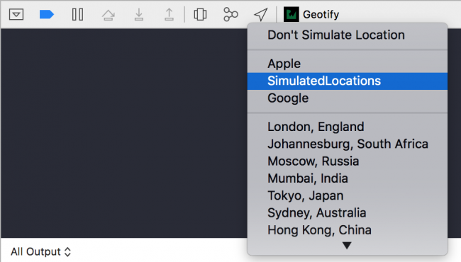
To begin simulating the locations in the GPX file, build and run the project. When the app launches the main view controller, go back to Xcode, select the Location icon in the Debug bar and choose SimulatedLocations:

Back in the app, use the Zoom button on the top-left of the navigation bar to zoom to the current location. Once you get close to the area, you’ll see the location marker moving repeatedly from the Googleplex to Apple, Inc. and back.

Test the app by adding a few geotifications along the path defined by the two waypoints. If you added any geotifications earlier in the tutorial before you enabled geofence registration, those geotifications will obviously not work, so you might want to clear them out and start afresh.

For the test locations, it’s a good idea to place a geotification roughly at each waypoint. Here’s a possible test scenario:

  • Google: Radius: 1000m, Message: "Say Bye to Google!", Notify on Exit
  • Apple: Radius: 1000m, Message: "Say Hi to Apple!", Notify on Entry
Note: Use the additional test locations provided to make it easy to add the locations.

Once you've added your geotifications, you’ll see a log in the console each time the location marker enters or leaves a geofence. If you activate the home button or lock the screen to send the app to the background, you’ll also see the logs each time the device crosses a geofence, though you obviously won't be able to verify that behavior visually.

Geofence triggered

Note: Location simulation works both in iOS Simulator and on a real device. However, the iOS Simulator can be quite inaccurate in this case; the timings of the triggered events do not coincide very well with the visual movement of the simulated location in and out of each geofence. You would do better to simulate locations on your device, or better still, take the app for a walk!

Notifying the User of Geofence Events

You've made a lot of progress with the app. At this point, it simply remains for you to notify the user whenever the device crosses the geofence of a geotification — so prepare yourself to do just that.

To obtain the note associated with a triggering CLCircularRegion returned by the delegate calls, you need to retrieve the corresponding geotification that was persisted in UserDefaults. This turns out to be trivial, as you can use the unique identifier you assigned to the CLCircularRegion during registration to find the right geotification.

In AppDelegate.swift, add the following import:

import UserNotifications

Next, add the following helper method at the bottom of the class:

func note(from identifier: String) -> String? {
  let geotifications = Geotification.allGeotifications()
  guard let matched = geotifications.filter {
    $0.identifier == identifier
  }
  .first else { return nil }
  return matched.note
}

This helper method retrieves the geotification note from the persistent store, based on its identifier, and returns the note for that geotification.

Now that you're able to retrieve the note associated with a geofence, you'll write code to trigger a notification whenever a geofence event fires and to use the note as the message.

Add the following statements to the end of application(_:didFinishLaunchingWithOptions:), just before the method returns:

let options: UNAuthorizationOptions = [.badge, .sound, .alert]
UNUserNotificationCenter.current()
  .requestAuthorization(options: options) { success, error in
  if let error = error {
    print("Error: \(error)")
  }
}

Finally, add the following method:

func applicationDidBecomeActive(_ application: UIApplication) {
  application.applicationIconBadgeNumber = 0
  UNUserNotificationCenter.current().removeAllPendingNotificationRequests()
  UNUserNotificationCenter.current().removeAllDeliveredNotifications()
}

The code you’ve added prompts the user for permission to enable notifications for this app. In addition, it does some housekeeping by clearing out all existing notifications.

Next, replace handleEvent(for:) with the following:

func handleEvent(for region: CLRegion!) {
  // Show an alert if application is active
  if UIApplication.shared.applicationState == .active {
    guard let message = note(from: region.identifier) else { return }
    window?.rootViewController?.showAlert(withTitle: nil, message: message)
  } else {
    // Otherwise present a local notification
    guard let body = note(from: region.identifier) else { return }
    let notificationContent = UNMutableNotificationContent()
    notificationContent.body = body
    notificationContent.sound = UNNotificationSound.default()
    notificationContent.badge = UIApplication.shared.applicationIconBadgeNumber + 1 as NSNumber
    let trigger = UNTimeIntervalNotificationTrigger(timeInterval: 1, repeats: false)
    let request = UNNotificationRequest(identifier: "location_change",
                                        content: notificationContent,
                                        trigger: trigger)
    UNUserNotificationCenter.current().add(request) { error in
      if let error = error {
        print("Error: \(error)")
      }
    }
  }
}

If the app is active, the code above simply shows an alert controller with the note as the message. Otherwise, it presents a location notification with the same message.

Build and run the project, and run through the test procedure covered in the previous section. Whenever your test triggers a geofence event, you’ll see an alert controller displaying the reminder note:

Send the app to the background by activating the Home button or locking the device while the test is running. You’ll continue to receive notifications periodically that signal geofence events:

And with that, you have a fully functional, location-based reminder app in your hands. And yes, get out there and take that app for a spin!

Note: When you test the app, you may encounter situations where the notifications don’t fire exactly at the point of boundary crossing.

This is because before iOS considers a boundary as crossed, there is an additional cushion distance that must be traversed and a minimum time period that the device must linger at the new location. iOS internally defines these thresholds, seemingly to mitigate the spurious firing of notifications in the event the user is traveling very close to a geofence boundary.

In addition, these thresholds seem to be affected by the available location hardware capabilities. From experience, the geofencing behavior is a lot more accurate when Wi-Fi is enabled on the device.

Where to Go From Here?

Congratulations! You’re now equipped with the basic knowledge you need to build your own geofencing-enabled apps!

You can download the completed version of the project using the Download Materials button at the top or bottom of this tutorial.

Geofencing is a powerful technology with many practical and far-reaching applications in such realms as marketing, resource management, security, parental control and even gaming — what you can achieve is really up to your imagination. You can read Apple's Region Monitoring to learn more.

I hope you’ve enjoyed this tutorial. Feel free to leave a comment or question below!

The post Geofencing with Core Location: Getting Started appeared first on Ray Wenderlich.

Metal Rendering Pipeline Tutorial

$
0
0

This is an excerpt taken from Chapter 3, “The Rendering Pipeline”, of our book Metal by Tutorials. This book will introduce you to graphics programming in Metal — Apple’s framework for programming on the GPU. You’ll build your own game engine in Metal where you can create 3D scenes and build your own 3D games. Enjoy!

In this tutorial, you’ll take a deep dive through the rendering pipeline and creatcme a Metal app that renders a red cube. Along the way, you’ll discover all of the hardware chips responsible for taking the 3D objects and turning them into the gorgeous pixels that you see on the screen.

The GPU and the CPU

All computers have a Central Processing Unit (CPU) that drives the operations and manages the resources on a computer. They also have a Graphics Processing Unit (GPU).

A GPU is a specialized hardware component that can process images, videos and massive amounts of data really fast. This is called throughput. The throughput is measured by the amount of data processed in a specific unit of time.

A CPU, on the other hand, can’t handle massive amounts of data really fast, but it can process many sequential tasks (one after another) really fast. The time necessary to process a task is called latency.

The ideal set up includes low latency and high throughput. Low latency allows for the serial execution of queued tasks so the CPU can execute the commands without the system becoming slow or unresponsive; and high throughput lets the GPU render videos and games asynchronously without stalling the CPU. Because the GPU has a highly parallelized architecture, specialized in doing the same task repeatedly, and with little or no data transfers, it’s able to process larger amounts of data.

The following diagram shows the major differences between the CPU and the GPU.

The CPU has a large cache memory and a few Arithmetic Logic Unit (ALU) cores. The low latency cache memory on the CPU is used for fast access to temporary resources. The GPU does not have much cache memory and there’s room for more ALU cores which only do calculations without saving partial results to memory.

Also, the CPU typically only has a handful of cores while the GPU has hundreds — even thousands of cores. With more cores, the GPU can split the problem into many smaller parts, each running on a separate core in parallel, thus hiding latency. At the end of processing, the partial results are combined and the final result returned to the CPU. But cores aren’t the only thing that matters!

Besides being slimmed down, GPU cores also have special circuitry for processing geometry and are often called shader cores. These shader cores are responsible for the beautiful colors you see on the screen. The GPU writes a whole frame at a time to fit the entire rendering window. It will then proceed to rendering the next frame as quickly as possible to maintain a good frame rate.

The CPU continues to issue commands to the GPU to keep it busy, but at some point, either the CPU will finish sending commands or the GPU will finish processing the commands it received. To avoid stalling, Metal on the CPU queues up multiple commands in command buffers and will issue new commands, sequentially, for the next frame without having to wait for the GPU to finish the first frame. This way, no matter who finishes the work first, there will be more work available to do.

The GPU part of the graphics pipeline starts once it’s received all of the commands and resources.

The Metal Project

You’ve been using Playgrounds to learn about Metal. Playgrounds are great for testing and learning new concepts. It’s important to understand how to set up a full Metal project. Because the iOS simulator doesn’t support Metal, you’ll use a macOS app.

Note: The project files for this tutorial’s challenge project also include an iOS target.

Create a new macOS app using the Cocoa App template.

Name your project Pipeline and check Use Storyboards. Leave the rest of the options unchecked.

Open Main.storyboard and select View under the View Controller Scene.

In the Identity inspector, change the view from NSView to MTKView.

This sets up the main view as a MetalKit View.

Open ViewController.swift. At the top of the file, import the MetalKit framework:

import MetalKit

Then, add this code to viewDidLoad():

guard let metalView = view as? MTKView else {
  fatalError("metal view not set up in storyboard")
}

You now have a choice. You can subclass MTKView and use this view in the storyboard. In that case, the subclass’s draw(_:) will be called every frame and you’d put your drawing code in that method. However, in this tutorial, you’ll set up a Renderer class that conforms to MTKViewDelegate and sets Renderer as a delegate of MTKView. MTKView calls a delegate method every frame, and this is where you’ll place the necessary drawing code.

Note: If you’re coming from a different API world, you might be looking for a game loop construct. You do have the option of extending CAMetalLayer instead of creating the MTKView. You can then use CADisplayLink for the timing; but Apple introduced MetalKit with its protocols to manage the game loop more easily.

The Renderer Class

Create a new Swift file named Renderer.swift and replace its contents with the following code:

import MetalKit

class Renderer: NSObject {
  init(metalView: MTKView) {
    super.init()
  }
}

extension Renderer: MTKViewDelegate {
  func mtkView(_ view: MTKView, drawableSizeWillChange size: CGSize) {
  }
  
  func draw(in view: MTKView) {
    print("draw")
  }
}

Here, you create an initializer and make Renderer conform to MTKViewDelegate with the two MTKView delegate methods:

  • mtkView(_:drawableSizeWillChange:): Gets called every time the size of the window changes. This allows you to update the render coordinate system.
  • draw(in:): Gets called every frame.

In ViewController.swift, add a property to hold the renderer:

var renderer: Renderer?

At the end of viewDidLoad(), initialize the renderer:

renderer = Renderer(metalView: metalView)

Initialization

First, you need to set up the Metal environment.

Metal has a major advantage over OpenGL in that you’re able to instantiate some objects up-front rather than create them during each frame. The following diagram indicates some of the objects you can create at the start of the app.

  • MTLDevice: The software reference to the GPU hardware device.
  • MTLCommandQueue: Responsible for creating and organizing MTLCommandBuffers each frame.
  • MTLLibrary: Contains the source code from your vertex and fragment shader functions.
  • MTLRenderPipelineState: Sets the information for the draw, like which shader functions to use, what depth and color settings to use and how to read the vertex data.
  • MTLBuffer: Holds data, such as vertex information, in a form that you can send to the GPU.

Typically, you’ll have one MTLDevice, one MTLCommandQueue and one MTLLibrary object in your app. You’ll also have several MTLRenderPipelineState objects that will define the various pipeline states, as well as several MTLBuffers to hold the data.

Before you can use these objects, however, you need to initialize them. Add these properties to Renderer:

static var device: MTLDevice!
static var commandQueue: MTLCommandQueue!
var mesh: MTKMesh!
var vertexBuffer: MTLBuffer!
var pipelineState: MTLRenderPipelineState!

These are the properties you need to keep references to the different objects. They are currently all implicitly unwrapped optionals for convenience, but you can change this after you’ve completed the initialization. Also, you won’t need to keep a reference to the MTLLibrary, so there’s no need to create it.

Next, add this code to init(metalView:) before super.init():

guard let device = MTLCreateSystemDefaultDevice() else {
  fatalError("GPU not available")
}
metalView.device = device
Renderer.commandQueue = device.makeCommandQueue()!

This initializes the GPU and creates the command queue. You’re using class properties for the device and the command queue to ensure that only one of each exists. In rare cases, you may require more than one — but in most apps, one will be plenty.

Finally, after super.init(), add this code:

metalView.clearColor = MTLClearColor(red: 1.0, green: 1.0,
                                     blue: 0.8, alpha: 1.0)
metalView.delegate = self

This sets metalView.clearColor to a cream color. It also sets Renderer as the delegate for metalView so that it calls the MTKViewDelegate drawing methods.

Build and run the app to make sure everything’s set up and working. If all’s well, you should see a plain gray window. In the debug console, you’ll see the word “draw” repeatedly. Use this to verify that your app is calling draw(in:) for every frame.

Note: You won’t see metalView’s cream color because you’re not asking the GPU to do any drawing yet.

Set Up the Data

A class to build 3D primitive meshes is always useful. In this tutorial, you’ll set up a class for creating 3D shape primitives, and you’ll add a cube to it.

Create a new Swift file named Primitive.swift and replace the default code with this:

import MetalKit

class Primitive {
  class func makeCube(device: MTLDevice, size: Float) -> MDLMesh {
    let allocator = MTKMeshBufferAllocator(device: device)
    let mesh = MDLMesh(boxWithExtent: [size, size, size], 
                       segments: [1, 1, 1],
                       inwardNormals: false, geometryType: .triangles,
                       allocator: allocator)
    return mesh
  }
}

This class method returns a cube.

In Renderer.swift, in init(metalView:), before calling super.init(), set up the mesh:

let mdlMesh = Primitive.makeCube(device: device, size: 1)
do {
  mesh = try MTKMesh(mesh: mdlMesh, device: device)
} catch let error {
  print(error.localizedDescription)
}

Then, set up the MTLBuffer that contains the vertex data you’ll send to the GPU.

vertexBuffer = mesh.vertexBuffers[0].buffer

This puts the data in an MTLBuffer. Now, you need to set up the pipeline state so that the GPU will know how to render the data.

First, set up the MTLLibrary and ensure that the vertex and fragment shader functions are present.

Continue adding code before super.init():

let library = device.makeDefaultLibrary()
let vertexFunction = library?.makeFunction(name: "vertex_main")
let fragmentFunction = library?.makeFunction(name: "fragment_main")

You’ll create these shader functions later in this tutorial. Unlike OpenGL shaders, these are compiled when you compile your project which is more efficient than compiling on the fly. The result is stored in the library.

Now, create the pipeline state:

let pipelineDescriptor = MTLRenderPipelineDescriptor()
pipelineDescriptor.vertexFunction = vertexFunction
pipelineDescriptor.fragmentFunction = fragmentFunction
pipelineDescriptor.vertexDescriptor = MTKMetalVertexDescriptorFromModelIO(mdlMesh.vertexDescriptor)
pipelineDescriptor.colorAttachments[0].pixelFormat = metalView.colorPixelFormat
do {
  pipelineState = try device.makeRenderPipelineState(descriptor: pipelineDescriptor)
} catch let error {
  fatalError(error.localizedDescription)
}

This sets up a potential state for the GPU. The GPU needs to know its complete state before it can start managing vertices. You set the two shader functions the GPU will call, and you also set the pixel format for the texture to which the GPU will write.

You also set the pipeline’s vertex descriptor. This is how the GPU will know how to interpret the vertex data that you’ll present in the mesh data MTLBuffer.

If you need to call different vertex or fragment functions, or use a different data layout, then you’ll need more pipeline states. Creating pipeline states is relatively time-consuming which is why you do it up-front, but switching pipeline states during frames is fast and efficient.

The initialization is complete and your project will compile. However, if you try to run it, you’ll get an error because you haven’t yet set up the shader functions.

Render Frames

In Renderer.swift, replace the print statement in draw(in:) with this code:

guard let descriptor = view.currentRenderPassDescriptor,
  let commandBuffer = Renderer.commandQueue.makeCommandBuffer(),
  let renderEncoder = 
    commandBuffer.makeRenderCommandEncoder(descriptor: descriptor) else {
    return
}

// drawing code goes here

renderEncoder.endEncoding()
guard let drawable = view.currentDrawable else {
  return
}
commandBuffer.present(drawable)
commandBuffer.commit()

This sets up the render command encoder and presents the view’s drawable texture to the GPU.

Drawing

On the CPU side, to prepare the GPU, you need to give it the data and the pipeline state. Then, you need to issue the draw call.

Still in draw(in:), replace the comment:

// drawing code goes here

with:

renderEncoder.setRenderPipelineState(pipelineState)
renderEncoder.setVertexBuffer(vertexBuffer, offset: 0, index: 0)
for submesh in mesh.submeshes {
  renderEncoder.drawIndexedPrimitives(type: .triangle,
                     indexCount: submesh.indexCount,
                     indexType: submesh.indexType,
                     indexBuffer: submesh.indexBuffer.buffer,
                     indexBufferOffset: submesh.indexBuffer.offset)
}

When you commit the command buffer at the end of draw(in:), this indicates to the GPU that the data and the pipeline are all set up and the GPU can take over.

The Rendering Pipeline

You finally get to investigate the GPU pipeline! In the following diagram, you can see the stages of the pipeline.

The graphics pipeline takes the vertices through multiple stages during which the vertices have their coordinates transformed between various spaces.

As a Metal programmer, you’re only concerned about the Vertex and Fragment Processing stages since they’re the only two programmable stages. Later in the tutorial, you’ll write both a vertex shader and a fragment shader. For all the non-programmable pipeline stages, such as Vertex Fetch, Primitive Assembly and Rasterization, the GPU has specially designed hardware units to serve those stages.

Next, you’ll go through each of the stages.

1 – Vertex Fetch

The name of this stage varies among various graphics Application Programming Interfaces (APIs). For example, DirectX calls it Input Assembling.

To start rendering 3D content, you first need a scene. A scene consists of models that have meshes of vertices. One of the simplest models is the cube which has 6 faces (12 triangles).

You use a vertex descriptor to define the way vertices will be read in along with their attributes such as position, texture coordinates, normal and color. You do have the option not to use a vertex descriptor and just send an array of vertices in an MTLBuffer, however, if you decide not to use one, you’ll need to know how the vertex buffer is organized ahead of time.

When the GPU fetches the vertex buffer, the MTLRenderCommandEncoder draw call tells the GPU whether the buffer is indexed. If the buffer is not indexed, the GPU assumes the buffer is an array and reads in one element at a time in order.

This indexing is important because vertices are cached for reuse. For example, a cube has twelve triangles and eight vertices (at the corners). If you don’t index, you’ll have to specify the vertices for each triangle and send thirty-six vertices to the GPU. This may not sound like a lot, but in a model that has several thousand vertices, vertex caching is important!

There is also a second cache for shaded vertices so that vertices that are accessed multiple times are only shaded once. A shaded vertex is one to which color was already applied. But that happens in the next stage.

A special hardware unit called the Scheduler sends the vertices and their attributes on to the Vertex Processing stage.

2 – Vertex Processing

In this stage, vertices are processed individually. You write code to calculate per-vertex lighting and color. More importantly, you send vertex coordinates through various coordinate spaces to reach their position in the final framebuffer.

Now it’s time to see what happens under the hood at the hardware level. Take a look at this modern architecture of an AMD GPU:

Going top-down, the GPU has:

  • 1 Graphics Command Processor: This coordinates the work processes.
  • 4 Shader Engines (SE): An SE is an organizational unit on the GPU that can serve an entire pipeline. Each SE has a geometry processor, a rasterizer and Compute Units.
  • 9 Compute Units (CU): A CU is nothing more than a group of shader cores.
  • 64 shader cores: A shader core is the basic building block of the GPU where all of the shading work is done.

In total, the 36 CUs have 2304 shader cores. Compare that to the number of cores in your quad-core CPU. Not fair, I know! :]

For mobile devices, the story is a little different. For comparison, take a look at the following image showing a GPU similar to those in recent iOS devices. Instead of having SEs and CUs, the PowerVR GPU has Unified Shading Clusters (USC). This particular GPU model has 6 USCs and 32 cores per USC for a total of only 192 cores.

Note: The iPhone X has the most recent mobile GPU which is entirely designed in-house by Apple. Unfortunately, Apple has not made the GPU hardware specifications public.

So what can you do with that many cores? Since these cores are specialized in both vertex and fragment shading, one obvious thing to do is give all the cores work to do in parallel so that the processing of vertices or fragments is done faster. There are a few rules, though. Inside a CU, you can only process either vertices or fragments at one time. Good thing there’s thirty-six of those! Another rule is that you can only process one shader function per SE. Having four SE’s lets you combine work in interesting and useful ways. For example, you can run one fragment shader on one SE and a second fragment shader on a second SE at one time. Or you can separate your vertex shader from your fragment shader and have them run in parallel but on different SEs.

It’s now time to see vertex processing in action! The vertex shader you’re about to write is minimal but encapsulates most of the necessary vertex shader syntax you’ll need.

Create a new file using the Metal File template and name it Shaders.metal. Then, add this code at the end of the file:

// 1
struct VertexIn {
  float4 position [[ attribute(0) ]];
};

// 2
vertex float4 vertex_main(const VertexIn vertexIn [[ stage_in ]]) {
  return vertexIn.position;
}

Going through this code:

  1. Create a struct VertexIn to describe the vertex attributes that match the vertex descriptor you set up earlier. In this case, just position.
  2. Implement a vertex shader, vertex_main, that takes in VertexIn structs and returns vertex positions as float4 types.

Remember that vertices are indexed in the vertex buffer. The vertex shader gets the current index via the [[ stage_in ]] attribute and unpacks the VertexIn struct cached for the vertex at the current index.

Compute Units can process (at one time) batches of vertices up to their maximum number of shader cores. This batch can fit entirely in the CU cache and vertices can thus be reused as needed. The batch will keep the CU busy until the processing is done but other CUs should become available to process the next batch.

As soon as the vertex processing is done, the cache is cleared for the next batches of vertices. At this point, vertices are now ordered and grouped, ready to be sent to the primitive assembly stage.

To recap, the CPU sent the GPU a vertex buffer that you created from the model’s mesh. You configured the vertex buffer using a vertex descriptor that tells the GPU how the vertex data is structured. On the GPU, you created a struct to encapsulate the vertex attributes. The vertex shader takes in this struct, as a function argument, and through the [[ stage_in ]] qualifier, acknowledges that position comes from the CPU via the [[ attribute(0) ]] position in the vertex buffer. The vertex shader then processes all the vertices and returns their positions as a float4.

A special hardware unit called Distributer sends the grouped blocks of vertices on to the Primitive Assembly stage.

3 – Primitive Assembly

The previous stage sent processed vertices grouped into blocks of data to this stage. The important thing to keep in mind is that vertices belonging to the same geometrical shape (primitive) are always in the same block. That means that the one vertex of a point, or the two vertices of a line, or the three vertices of a triangle, will always be in the same block, hence a second block fetch will never be necessary.

Along with vertices, the CPU also sends vertex connectivity information when it issues the draw call command, like this:

renderEncoder.drawIndexedPrimitives(type: .triangle,
                          indexCount: submesh.indexCount,
                          indexType: submesh.indexType,
                          indexBuffer: submesh.indexBuffer.buffer,
                          indexBufferOffset: 0)

The first argument of the draw function contains the most important information about vertex connectivity. In this case, it tells the GPU that it should draw triangles from the vertex buffer it sent.

The Metal API provides five primitive types:

  • point: For each vertex rasterize a point. You can specify the size of a point that has the attribute [[point_size]] in the vertex shader.
  • line: For each pair of vertices rasterize a line between them. If a vertex was already included in a line, it cannot be included again in other lines. The last vertex is ignored if there are an odd number of vertices.
  • lineStrip: Same as a simple line except that the line strip connects all adjacent vertices and forms a poly-line. Each vertex (except the first) is connected to the previous vertex.
  • triangle: For every sequence of three vertices rasterize a triangle. The last vertices are ignored if they cannot form another triangle.
  • triangleStrip: Same as a simple triangle except adjacent vertices can be connected to other triangles as well.

There is one more primitive type called a patch but this needs a special treatment and cannot be used with the indexed draw call function.

The pipeline specifies the winding order of the vertices. If the winding order is counter-clockwise, and the triangle vertex order is counter-clockwise, it means they are front-faced. Otherwise, they are back-faced and can be culled since we cannot see their color and lighting.

Primitives will be culled when they are totally occluded by other primitives, however, when they are only partially off-screen, they’ll be clipped.

For efficiency, you should specify winding order and enable back-face culling.

At this point, primitives are fully assembled from connected vertices and they move on to the rasterizer.

4 – Rasterization

There are two modern rendering techniques currently evolving on separate paths but sometimes used together: ray tracing and rasterization. They are quite different; both have pros and cons.

Ray tracing is preferred when rendering content that is static and far away, while rasterization is preferred when the content is closer to the camera and more dynamic.

With ray tracing, for each pixel on the screen, it sends a ray into the scene to see if there’s an intersection with an object. If yes, change the pixel color to that object’s color, but only if the object is closer to the screen than the previously saved object for the current pixel.

Rasterization works the other way around: for each object in the scene, send rays back into the screen and check which pixels are covered by the object. Depth information is kept the same way as for ray tracing, so it will update the pixel color if the current object is closer than the previously saved one.

At this point, all connected vertices sent from the previous stage need to be represented on a two-dimensional grid using their X and Y coordinates. This step is known as the triangle setup.

Here is where the rasterizer needs to calculate the slope or steepness of the line segments between any two vertices. When the three slopes for the three vertices are known, the triangle can be formed from these three edges.

Next, a process called scan conversion runs on each line of the screen to look for intersections and to determine what is visible and what is not. To draw on the screen at this point, only the vertices and the slopes they determine are needed. The scan algorithm determines if all the points on a line segment, or all the points inside of a triangle are visible, in which case the triangle is filled with color entirely.

For mobile devices, the rasterization takes advantage of the tiled architecture of PowerVR GPUs by rasterizing the primitives on a 32×32 tile grid in parallel. In this case, 32 is the number of screen pixels assigned to a tile but this size perfectly fits the number of cores in a USC.

What if one object is behind another object? How can the rasterizer determine which object to render? This hidden surface removal problem can be solved by using stored depth information (early-Z testing) to determine whether each point is in front of other points in the scene.

After rasterization is finished, three more specialized hardware units take the stage:

  • A buffer called Hierarchical-Z is responsible for removing fragments that were marked for culling by the rasterizer.
  • The Z and Stencil Test unit then removes non-visible fragments by comparing them against the depth and stencil buffer.
  • Finally, the Interpolator unit takes the remaining visible fragments and generates fragment attributes from the assembled triangle attributes.

At this point, the Scheduler unit again dispatches work to the shader cores, but this time it’s the rasterized fragments sent for Fragment Processing.

5 – Fragment Processing

Time for a quick review of the pipeline.

  • The Vertex Fetch unit grabs vertices from the memory and passes them to the Scheduler unit.
  • The Scheduler unit knows which shader cores are available so it dispatches work on them.
  • After work is done, the Distributer unit knows if this work was Vertex or Fragment Processing.
  • If it was Vertex Processing work, it sends the result to the Primitive Assembly unit. This path continues to the Rasterization unit and then back to the Scheduler unit.
  • If it was Fragment Processing work, it sends the result to the Color Writing unit.
  • Finally, the colored pixels are sent back to the memory.

The primitive processing in the previous stages was sequential because there is only one Primitive Assembly unit and one Rasterization unit. However, as soon as fragments reach the Scheduler unit, work can be forked (divided) into many tiny parts, and each part is given to an available shader core.

Hundreds or even thousands of cores are now doing parallel processing. When the work is finished, the results will be joined (merged) and sent to the memory, again sequentially.

The fragment processing stage is another programmable stage. You create a fragment shader function that will receive the lighting, texture coordinate, depth and color information that the vertex function output.

The fragment shader output is a single color for that fragment. Each of these fragments will contribute to the color of the final pixel in the framebuffer. All the attributes are interpolated for each fragment.

For example, to render this triangle, the vertex function would process three vertices with the colors red, green and blue. As the diagram shows, each fragment that makes up this triangle is interpolated from these three colors. Linear interpolation simply averages the color at each point on the line between two endpoints. If one endpoint has red color, and the other has green color, the midpoint on the line between them will be yellow. And so on.

The interpolation equation is parametric and has this form, where parameter p is the percentage (or a range from 0 to 1) of a color’s presence:

newColor = p * oldColor1 + (1 - p) * oldColor2

Color is easy to visualize, but all the other vertex function outputs are also similarly interpolated for each fragment.

Note: If you don’t want a vertex output to be interpolated, add the attribute [[ flat ]] to its definition.

In Shaders.Metal, add the fragment function to the end of the file:

fragment float4 fragment_main() {
  return float4(1, 0, 0, 1);
}

This is the simplest fragment function possible. You return the interpolated color red in the form of a float4. All the fragments that make up the cube will be red.

The GPU takes the fragments and does a series of post-processing tests:

  • alpha-testing determines which opaque objects are drawn and which are not based on depth testing.
  • In the case of translucent objects, alpha-blending will combine the color of the new object with that already saved in the color buffer previously.
  • scissor testing checks whether a fragment is inside of a specified rectangle; this test is useful for masked rendering.
  • stencil testing checks how the stencil value in the framebuffer where the fragment is stored, compares to a specified value we choose.
  • In the previous stage early-Z testing ran; now a late-Z testing is done to solve more visibility issues; stencil and depth tests are also useful for ambient occlusion and shadows.
  • Finally, antialiasing is also calculated here so that final images that get to the screen do not look jagged.

6 – Framebuffer

As soon as fragments have been processed into pixels the Distributer unit sends them to the Color Writing unit. This unit is responsible for writing the final color in a special memory location called the framebuffer. From here, the view gets its colored pixels refreshed every frame. But does that means the color is written to the framebuffer while being displayed on the screen?

A technique called double-buffering is used to solve this situation. While the first buffer is being displayed on the screen, the second one is updated in the background. Then, the two buffers are swapped, and the second one is displayed on the screen while the first one is updated, and the cycle continues.

Whew! That was a lot of hardware information to take in. However, the code you’ve written is what every Metal renderer uses, and despite just starting out, you should begin to recognize the rendering process when you look at Apple’s sample code.

Build and run the app, and your app will render this red cube:

Notice how the cube is not square. Remember that Metal uses Normalized Device Coordinates (NDC) that is -1 to 1 on the X axis. Resize your window, and the cube will maintain a size relative to the size of the window.

Send Data to the GPU

Metal is all about gorgeous graphics and fast and smooth animation. As a next step, you’ll make your cube move up and down the screen. To do this, you’ll have a timer that updates every frame and the cube’s position will depend on this timer. The vertex function is where you update vertex positions so you’ll send the timer data to the GPU.

At the top of Renderer, add the timer property:

var timer: Float = 0

In draw(in:), just before:

renderEncoder.setRenderPipelineState(pipelineState)

add:

// 1
timer += 0.05
var currentTime = sin(timer)
// 2
renderEncoder.setVertexBytes(&currentTime, 
                              length: MemoryLayout<Float>.stride, 
                              index: 1)
  1. You add the timer to every frame. You want your cube to move up and down the screen, so you’ll use a value between -1 and 1. Using sin() is a great way to achieve this as sine values are always -1 to 1.
  2. If you’re only sending a small amount of data (less than 4kb) to the GPU, setVertexBytes(_:length:index:) is an alternative to setting up a MTLBuffer. Here, you set currentTime to be at index 1 in the buffer argument table.

In Shaders.metal, replace the vertex function with:

vertex float4 vertex_main(const VertexIn vertexIn [[ stage_in ]],
                          constant float &timer [[ buffer(1) ]]) {
  float4 position = vertexIn.position;
  position.y += timer;
  return position;
}

Here, your vertex function receives the timer as a float in buffer 1. You add the timer value to the y position and return the new position from the function.

Build and run the app, and you now have an animated cube!

With just a few bits of code, you’ve learned how pipelines work and you even added a little animation.

Where to Go From Here?

If you want to check out the completed project for this tutorial, you can find it in the final directory of the downloads for this tutorial.

If you enjoyed what you learned in this tutorial, why not check out our Metal by Tutorials book, available on our store?

This book will introduce you to low-level graphics programming in Metal — Apple’s framework for programming on the graphics processing unit (GPU). As you progress through this book, you’ll learn many of the fundamentals that go into making a game engine and gradually put together your own engine.

Once your game engine is complete, you’ll be able to put together 3D scenes and program your own simple 3D games. Because you’ll have built your 3D game engine from scratch, you’ll be able to customize every aspect of what you see on your screen.

But beyond the technical definition, Metal is the most appropriate way to use the GPU’s parallel processing power to visualize data or solve numerical challenges. It’s also tailored to be used for machine learning, image/video processing or, as this book describes, graphics rendering.

This is a perfect resource for intermediate Swift developers interested in learning 3D graphics or gaining a deeper understanding of how game engines work.

To celebrate the launch of the book, it’s currently on sale as part of our Game On book launch event. But don’t wait too long, as this deal is only good until Friday, June 8th!

If you have any questions or comments on this tutorial, feel free to join the discussion below!

The post Metal Rendering Pipeline Tutorial appeared first on Ray Wenderlich.

TapTargetView for Android Tutorial

$
0
0

TapTargetView for Android Tutorial

Releasing a new feature for your app sounds exciting, and you can’t wait to have your users use it. But what if your users didn’t use that feature at all, or worst case they don’t even know that the feature exists in your app. That sounds pretty scary, right?

You don’t have to be afraid though because today you will learn how you can highlight that new feature with an explanation. Your users will understand what the feature is and what its function is, and this will help you build a positive relationship with them.

You will be using a third party library named TapTargetView. You can use this library to help you to better highlight your app features to your users. You will build an app called What2eat where you will learn the following things:

  • How to add the TapTargetView library to your project.
  • How you can use the TapTargetView library to highlight menu items on the Android Toolbar, AlertDialog buttons, and standard Android buttons.
  • How you can highlight a feature to your users only once so that you don’t annoy them every time they use your app.

Prerequisites: This tutorial assumes that you have the basics of Android development with Kotlin under your belt. If you’re new to Android Development, please go through Beginning Android Development with Kotlin to understand the basics. If you’re new to Kotlin, please check out this introduction to Kotlin tutorial.

Getting Started

Download the starter project using the download button at the top or bottom of the tutorial. Open up Android Studio 3.0.1 or later, select the second option Open an existing Android Studio project and navigate to and select the starter project folder.

Android studio welcome page

Once the initial Gradle build is complete, build and run the app to see the current state of the app.

The first screen shows you a list of yummy food inside a RecyclerView.

what2eat screen

Note: If you’re new to Android Recyclerview, please go through Android RecyclerView Tutorial with Kotlin to understand the basics.

You have a Settings screen that you can access from the app menu that shows the app icon and version:

what2eat setting page

Tap a food item on the first screen to show a detail screen:

what2eat screen

From the detail screen, you can share the food item or tap on “Visit Store” to open your device browser to this link: https://www.freshdirect.com/index.jsp

what2eat intent chooser

what2eat visit store

Adding the TapTargetView Dependency

Open the build.gradle (Module:app) file to add the TapTargetView library dependency.

dependencies {
  ...
  implementation 'com.getkeepsafe.taptargetview:taptargetview:1.11.0'
}

Click on Sync now to sync your project Gradle files and so you’re able to use these libraries.

Android studio project sync

Now let’s get started working with TapTargetView.

Working with TapTargetView

In this section, you will learn how you can use the library with Toolbar, AlertDialog, and ImageView items.

TapTargetView with a Toolbar

First you’ll learn how you can use TapTargetView to highlight menu items on a Toolbar.

Open up MainActivity and add the following code below this line

recyclerView.adapter = FoodAdapter(this, foodName, foodImage)
// 1
TapTargetView.showFor(this,
    // 2
    TapTarget.forToolbarOverflow(toolbar, getString(R.string.label_app_settings),
        getString(R.string.description_app_setting))
        // 3
        .cancelable(false)
        // 4
        .tintTarget(true),
    // 5
    object : TapTargetView.Listener() {
      override fun onTargetClick(view: TapTargetView) {
        super.onTargetClick(view)
        view.dismiss(true)
      }
    })

Use Alt+Enter on PC or Option+Return on Mac to pull in the necessary imports.

Let’s go through this code step by step:

  1. TapTargetView.showFor: You always start with this, and you pass the current Context as the first argument.
  2. TapTarget.forToolbarOverflow: Here you choose to highlight the overflow menu item by passing these three arguments: the Toolbar that has the overflow menu item, the title of the menu item, and a simple description about the function of the menu item.
  3. cancelable(boolean): You pass a boolean value (true) if you want to dismiss the highlight circle when tapping on an empty area or (false) to prevent that from happening.
  4. tintTarget(boolean): You pass a boolean value (true) if you want to tint the view’s icon color or (false) if you want to make it white.
  5. TapTargetView.Listener: Here is where you write the logic that you want to execute when you tap on the overflow menu item. Otherwise you can dismiss the highlight circle using view.dismiss(true)

Build and run the app to TapTargetView in action on the Toolbar.

what2eat overflow highlight

It looks cool right! :]

Now go ahead and create a highlight circle for the search menu item by adding the following code below the highlight circle for the overflow menu item.

TapTargetView.showFor(this, TapTarget.forToolbarMenuItem(toolbar, R.id.action_search,
    getString(R.string.label_search), getString(R.string.description_search))
    .cancelable(false).tintTarget(true), object : TapTargetView.Listener() {
  override fun onTargetClick(view: TapTargetView) {
    super.onTargetClick(view)
    view.dismiss(true)
  }
})

Here you use TapTarget.forToolbarMenuItem because you want the highlight circle to appear on the search menu icon. When you tap on the search menu icon you will dismiss the highlight circle.

Build and run the app to see the output.

what2eat search highlight

TapTargetView with an AlertDialog

In this section, you will learn how you can use TapTargetView to show a highlight circle inside an AlertDialog.

Open up MainActivity and add the following method below onCreate().

override fun onBackPressed() {
  // 1
  val alertDialog = AlertDialog.Builder(this).create()
  // 2
  alertDialog.setMessage("Are you sure you want to exit ${resources.getString(R.string.app_name)}")
  // 3
  alertDialog.setButton(AlertDialog.BUTTON_POSITIVE, getString(R.string.label_ok),
      { _, _ ->
        val intent = Intent(Intent.ACTION_MAIN)
        intent.addCategory(Intent.CATEGORY_HOME)
        intent.flags = Intent.FLAG_ACTIVITY_NEW_TASK
        startActivity(intent)
      })
  // 4
  alertDialog.setButton(AlertDialog.BUTTON_NEGATIVE, getString(R.string.label_no),
      { dialogInterface, _ ->
        dialogInterface.dismiss()
      })
  // 5
  alertDialog.show()
  // 6
  TapTargetView.showFor(alertDialog,
      // 7
      TapTarget.forView(alertDialog.getButton(DialogInterface.BUTTON_POSITIVE),
          getString(R.string.label_exit_app),
          getString(R.string.description_exit))
          .cancelable(false).tintTarget(false), object : TapTargetView.Listener() {
    // 8        
    override fun onTargetClick(view: TapTargetView) {
      super.onTargetClick(view)
      view.dismiss(true)
    }
  })
}

Here’s a step-by-step breakdown:

You’ve overridden onBackPressed(), so that when you tap on your device physical back button, it will show an AlertDialog with the highlight circle.

  1. val alertDialog: You define an AlertDialog.
  2. alertDialog.setMessage: You give the AlertDialog a message.
  3. alertDialog.setButton: You give the AlertDialog a positive button, once you tap on that button you will exit the app.
  4. alertDialog.setButton: You give the AlertDialog a negative button, and once you tap on that button, you will dismiss the dialog.
  5. alertDialog.show(): You need to call show() for the dialog to appear on the device screen.
  6. TapTargetView.showFor: Here you want to show the highlight circle on the AlertDialog.
  7. TapTarget.forView: You use this method to show the highlight circle on the positive button of the AlertDialog.
  8. override fun onTargetClick(...): You dismiss the highlight circle on the first tap of the positive button.

Build and run the app, then tap on the physical device back button to see the new highlight circle.

what2eat dialog highlight

TapTargetView with an ImageView

In this section, you will learn how you can use TapTargetView to show a highlight circle on an ImageView.

Open up SettingsActivity and add the following code at the bottom of the onCreate() function.

TapTargetView.showFor(this, TapTarget.forView(ivAppIcon, getString(R.string.label_icon),
    "This is the icon that is currently being used for ${tvAppName.text}").
    tintTarget(false).cancelable(false), object : TapTargetView.Listener() {
  override fun onTargetClick(view: TapTargetView) {
    super.onTargetClick(view)
    view.dismiss(true)
  }
})

Here you show the highlight circle on ivAppIcon, and you can dismiss the highlight circle once you tap on it.

Build and run the app and go to the Settings screen to see the result.

what2eat setting highlight

TapTargetSequence on Multiple items

In this section, you will learn how to use a new class from the TapTargetView library, called TapTargetSequence. You can use this class when you want to show the highlight circle on many views one-by-one in a sequential fashion.

Open up FoodDetailActivity and add the following codes at the bottom of onCreate().

// 1
TapTargetSequence(this)
    // 2
    .targets(
        TapTarget.forView(btnShare, getString(R.string.label_share_food),
            getString(R.string.description_share_food))
            .cancelable(false).transparentTarget(true).targetRadius(70),
        TapTarget.forView(btnStore, getString(R.string.label_buy_food),
            getString(R.string.description_buy_food)).cancelable(false).
            transparentTarget(true).targetRadius(70),
        TapTarget.forToolbarNavigationIcon(toolbar, getString(R.string.label_back_arrow),
        getString(R.string.description_back_arrow)).cancelable(false)
            .tintTarget(true))
    // 3
    .listener(object : TapTargetSequence.Listener {
      override fun onSequenceStep(lastTarget: TapTarget?, targetClicked: Boolean) {
       }
      // 4
      override fun onSequenceFinish() {
        Toast.makeText(this@FoodDetailActivity, getString(R.string.msg_tutorial_complete),
            Toast.LENGTH_LONG).show()
      }
      // 5
      override fun onSequenceCanceled(lastTarget: TapTarget) {
      }
    })
    // 6
    .start()

Here’s a step-by-step breakdown:

  1. TapTargetSequence(this): Here you define a TapTargetSequence by passing Context as an argument.
  2. targets(): Here is where you include the views that you want the highlight circle to appear on them. You will pass the view name, title, and description.
  3. onSequenceStep: You can perform a certain action once you complete a sequence such as showing a Toast message.
  4. onSequenceFinish: Once you complete all the steps in the sequence you can show a Toast message indicating that the sequence is complete.
  5. onSequenceCanceled: Called when you try to cancel a sequence such as tapping on an empty area to dismiss the highlight circle.
  6. start(): This is the final part that you need to call for the highlight circle sequence to appear on the screen. Otherwise the sequence won’t appear.

Build and run the app and go to a detail screen to see the result.

what2eat gif

Preventing Multiple Highlights

It seems that the highlight circle sequence appears every time you navigate to the FoodDetailActivity screen, how can you prevent that from happening?

One solution is to use a persistence mechanism like SharedPreferences to save whether or not the highlighting has been seen.

Create a new Kotlin file in the base app package and name it StatusUtils. Add the following code inside the file:

object StatusUtils {
  // 1
  fun storeTutorialStatus(context: Context, show: Boolean) {
    val preferences = context.getSharedPreferences("showTutorial", Context.MODE_PRIVATE)
    val editor = preferences.edit()
    editor.putBoolean("show", show)
    editor.apply()
  }

  // 2
  fun getTutorialStatus(context: Context): Boolean {
    val preferences = context.getSharedPreferences("showTutorial", Context.MODE_PRIVATE)
    return preferences.getBoolean("show", true)
  }
}

Here’s a step-by-step breakdown of the code in the new file:

  1. storeTutorialStatus(): This function takes two parameters: a Context and a Boolean. You use this function to store the status of the highlight circle sequence inside SharedPreferences.
  2. getTutorialStatus(): This function takes a Context as an argument, and you use this function to determine whether to show or hide the highlight circle sequence based on the boolean value that you stored using storeTutorialStatus().

Open up FoodDetailActivity.kt file and change TapTargetSequence to include the two functions from StatusUtils:

if (StatusUtils.getTutorialStatus(this)) {
  TapTargetSequence(this)
      .targets(
          TapTarget.forView(btnShare, getString(R.string.label_share_food),
              getString(R.string.description_share_food))
              .cancelable(false).transparentTarget(true).targetRadius(70),
          TapTarget.forView(btnStore, getString(R.string.label_buy_food),
              getString(R.string.description_buy_food)).cancelable(false).transparentTarget(true).targetRadius(70),
          TapTarget.forToolbarNavigationIcon(toolbar, getString(R.string.label_back_arrow),
              getString(R.string.description_back_arrow)).cancelable(false)
              .tintTarget(true)).listener(object : TapTargetSequence.Listener {
        override fun onSequenceStep(lastTarget: TapTarget?, targetClicked: Boolean) {
        }

        override fun onSequenceFinish() {
          Toast.makeText(this@FoodDetailActivity, getString(R.string.msg_tutorial_complete),
              Toast.LENGTH_LONG).show()
          StatusUtils.storeTutorialStatus(this@FoodDetailActivity, false)
        }

        override fun onSequenceCanceled(lastTarget: TapTarget) {
        }
      }).start()
}

Here you first check the status of the highlight circle sequence. If the status is true the sequence will start, and you then store the status of the sequence as false once it reaches onSequenceFinish().

If the status in SharedPreferences is false, you will not see the highlight circle sequence anymore when you navigate to the FoodDetailActivity screen.

Build and run the app to see the result. The first time you navigate to a detail screen, you will see the highlight sequence. Subsequent visits will not show the highlight sequence.

what2eat gif

You can use a similar technique with SharedPreferences to determine whether or not to show the other highlights in the app once your user has seen them one or more times.

Where To Go From Here?

You can download the completed sample project using the download button at the top or bottom of the tutorial.

Be sure to check out TapTargetView GitHub documentation to find out all the things you can do to customize highlight circles to better match your app requirements.

We hope you enjoyed this tutorial on TapTargetView, and if you have any questions or comments, please join the forum discussion below!

The post TapTargetView for Android Tutorial appeared first on Ray Wenderlich.

Screencast: Dynamic Type: Managing Layout

Oculus Go Overview

$
0
0

The Oculus Go Overview

At this year’s F8 developer conference, Facebook made a bit of a splash. Their long-awaited VR headset — Oculus Go — was released to the public for an affordable price of $199.99. In one stroke, Oculus Go addressed all of the issues that I’ve previously had with other VR headsets: This new headset has the hardware built right into it, so I was no longer tethered to my computer. With the headset being so affordable, there was less financial risk on my part. And, while it doesn’t have the horsepower of my computer backing it, the headset does provide the essence of VR.

The big question: Is it worth the money that Facebook is asking or is it just another piece of tech destined for the attic?

In this article, I’ll provide an overview of the headset and maybe, just maybe, I’ll show you how to get it up and running with the latest version of Unity so that you can build your own VR worlds.

Setting Up the Oculus Go Headset

My Oculus Go experience started with a package left on my doorstep. It was a bit dense, heavier than I expected for what essentially is a headset with a matching pointer. Paying coach rate for VR, I expected to receive a cheap headset thrown together from backroom parts but, opening the box and inspecting the device, it was clear that the headset is more than a plastic knockoff of its older brother.

The Oculus Go Overview

The box comes with a headset and a simple wand controller, along with a few accessories. I find the headset to be a good size for my face. It has a bit of weight to it — enough to make it feel snug. It also comes with an insert so that I can wear glasses while using it; unfortunately, the headset presses my glasses tight against my ears. For short sessions, this isn’t a problem but, after an hour of using it, my ears begin to throb. Granted there are lots of straps to adjust to decrease the tightness, but I have yet to find my sweet spot.

The headset’s screen is 5.5 inches with a resolution of 2560 x 1440 pixels. It looks good, with the projected image being clear with bright colors that don’t look muddled; however, at times, I can see the pixels — it’s most noticeable when there’s a lot of white being displayed. Also, at times, I find occasional light seepage around my nose; most of the time, I don’t notice it but, when I do, it can be distracting.

The headset also features spatial sound. This means I get the full surround sound experience, and it does the job nicely. The sound is piped through speakers, which means everyone nearby will hear any stray gunshots aimed at me. You can provide your own headphones, however; having used both ear buds and stereo phones, I have no issues while wearing the device.

The Oculus Go Overview

I didn’t know what to expect from the wand controller. It features a touchpad, two buttons and a trigger. Looking at it reminds me of the Wiimote, which isn’t a good thing; the Wiimote was always a mushy experience for me so I was shocked, despite its appearance, to discover that the Oculus Go controller is quite good. It feels like I’m simply holding a laser pointer while in VR. There are times when the pointer loses its orientation, but it’s quite easy to readjust by means a settings option. My only complaint is with the touchpad. Sometimes, it doesn’t feel responsive and, other times, it’s too responsive. Gestures are often muddled. Gestures tend to be confused so a simple vertical swipe won’t register or register as a different gesture. Thankfully, the rest of the controller makes up for the touchpad’s shortcomings.

Before I can power on the headset, I need to install the Oculus Go app on my phone, which is available on iOS and Android respective app stores. Naturally, being a Facebook product, I need to log in with my Facebook account. Unfortunately, this is a requirement as opposed to a suggestion. There’s also a bunch of privacy settings regarding whether I want to connect with my friends and share VR experiences via the social media platform.

Note to Facebook: When I’m using the Oculus Go headset, I’m basically wearing a brick on my face. Socialization is the last thing on my mind.

Unfortunately, even though I am mostly pleased with the look and feel of the headset and wand, my initial experience using them isn’t ideal. The headset has just enough power to get me through the installation process and then it keeps switching to sleep mode. I initially think that the headset is broken because, no matter how I charge it, the headset won’t stay active for more than thirty seconds. I have to charge the device to 100%, after which the sleep issue goes away. Thankfully, the online support forums and Oculus support team are helpful. Submitting a support request was as easy as filing an online ticket, and then working through the issues in a chat interface.

Once the headset is up and running, I really enjoy using it. There are lots of freebies you can download to get started. Some are expereiences like riding a bobsled or a rollercoaster. Additional games cost five to ten dollars. Like other mobile games, some feature microtransactions and the free games have a most of their features gated behind paywalls.

As you might expect, however, being a low-cost VR device, the headset is a bit limited. If you are coming from using the more expensive Oculus Rift or HTC Vive, you’ll be used to six degrees of movement — that is, full rotation and translation. With Oculus Go, you have only three degrees of movement. Moreover, without anything to track your position in real space (a.k.a. meat space), there’s no way for Oculus Go to determine certain movements. This means that, when I move forward in real life, my position in the VR world remains static. If you are used to the more expensive VR headsets, this may feel constrained.

The real question, though: How are the games?

The Games

Out of the box, Oculus Go is said to feature over a thousand games. Oculus Go uses a custom Android OS specifically tailored for the hardware. This means that games developed using Gear VR work out-of-the-box with Oculus Go, which is evident because some games reference Gear VR device controls while failing to even mention the updated Oculus Go controls. In time, this will change as developers update their games but, for the meantime, early adopters have to get used to misleading instructions or prompts.

Purchasing games is done through the integreated app store. Once you’ve setup your account, it’s just a matter of searching the store, finding an app, and clicking the download button. Some cost money and you’ll quickly discover, like mobile, that the free apps aren’t really free.

My biggest gripe with the store is that apps with DLC are mentioned, but store doesn’t list the DLC nor the DLC prices. You’ll never know if whether an app is featuring a one time unlock or

Here are some of the games I played:

Coaster Combat

If you’re going to go on VR, you’re going to go on a few coaster rides. Them’s the rules. Coaster Combat is a fun twist on the genre in that you not only ride coasters (well, mine carts actually), but also shoot at targets and other riders. It’s an enjoyable version of a typical coaster game and the art style is well done. I did experience a bit of slow down, which is a little jarring, but overall, it was a fun experience. It gives you the feeling of motion of a rollercoaster with something to do (shooting targets) as opposed to being a passive experience.

Coaster Combat Store Page

Ultrawings

One of my bucket-list items in life is to earn my pilot’s license. Unfortunately, flying planes is expensive. Until the kiddos are through college, I can play Ultrawings instead. Granted, it’s a very simplified version of flying, but it really gives you the sense of movement. There’s nothing quite like banking your plane over the ocean and looking out the window. The simulated motion can be intense and you may feel a little sick. Thankfully, you can customize how much you see from your cockpit, minimizing the motion intensity.

Ultrawings Store Page

Rush

Like Ultrawings, Rush features airplanes but, instead of flying them, you jump out of them. You essentially ride a wing suit through rings while avoiding cliffs, houses and other stationary objects. The game loop is fun, but it’s the lobby system that impressed me. You wait in a plane with other competitors and there are Nerf-like guns that fire suction darts. You basically shoot at each other and other targets with the guns. It’s really silly, but a fun way to get into a match.

Rush Store Page

Overtake: Traffic Racing

Being stuck in traffic, I often have daydreams of dodging and weaving without a single thought of safety. Overtake: Traffic Racing scratches that itch. The game puts you on a variety of maps where you must slalom through traffic to beat the clock or see how close you can get to other cars without hitting them. Out of all the games I’ve played, this one feels most like a traditional console game. This is probably due to the fact that movement is limited to just a few lanes and there’s not a lot of variation — you are always driving straight ahead. That said, the controls are tight and is fun to play.

Overtake Traffic Racing Store Page

Freebies

There are also loads of free games available. Some of these games feature in-app purchases like your typical mobile game, but others also have integrated ads. The ads are a real problem. Whereas you can just put down your phone when an ad pops up, in VR I feel like I’m forced to watch them. It’s an uncomfortable experience and not worth the price of admission.

Some games also require certain permissions: Accessing the file system or using your microphone, for example. One game even wanted to acccess my celluar data. These are clearly holdovers from the apps being ported to Oculus Go, but it still feels intrusive while also vague; with Facebook being under the microscope for all its privacy issues, it’d be nice of them to require better explanations for the requests.

Developing on the Oculus Go With Unity

The big question you may be wondering: “How’s the development?” It’s not too bad, in my estimation, although you are limited in several ways that you aren’t with some other devices:

  • First, Oculus Go doesn’t haven access to Google Play Services; it’s just not part of that environment.
  • Next, since the device isn’t a smart phone, certain app behaviors, such as phone notifications, won’t appear on the device.
  • The device doesn’t have access to a camera, since there isn’t one.
  • The device also doesn’t have access to a head-mounted display (HMD) touchpad. The HMD touchpad is a touch-sensitive region on the side of the Gear VR headset that allows for interaction. In fact, some Oculus Go games even reference the surface in their instructions. It’s just not available for developers to use on Oculus Go because, like the camera, it’s not part with the headset.

Getting Started

Note: To get started developing with Oculus Go, you need your version of Unity 2018 configured to produce Android games. This will require you to install the Java Development Kit, Android Studio, and to make a bunch of configuration changes to produce an .apk file. If you’ve never built an Android game, you’ll want to take these steps first. There are lots of resources on the web to walk you through the process.

After you’re set up to start developing, you’ll need to put your Oculus Go headset into developer mode, otherwise you won’t be able to test your games. You’ll do this from the main Oculus app on your phone. This is the same app you used to register headset. In the settings of the app, you select your paired Oculus Go headset, and then select More Settings. From that menu, select Developer Mode and then switch it to On.

At this point, you’ll be prompted to set up your developer account the Oculus webiste. This will require to fill out some information about your company. Once saved, you must return to the app and turn the developer mode on. If you don’t get the prompt, that means that your headset it ready to roll.

Now go ahead and make an amazing VR game. Or you can download one our VR apps from our existing tutorials. Don’t worry, we’ll wait. :]

Configuring Settings

With your game ready, you need to make a few tweaks to the settings.

First, open the Build Settings and make sure your Unity project is using the Android platform. From the Build Settings menu, change Texture Compression to ASTC:

Next, click the Player Settings button and select the Android tab. First, you need to indicate that your game supports VR and you also need to select a VR SDK. You can find this in XR Settings. Simply click the Virtual Reality Supported checkbox and then click the plus sign under Virtual Reality SDKs. Make sure to select Oculus as the SDK:

Now, for the Quality Settings. From the menu bar, select Edit ▸ Project Settings ▸ Quality. Oculus suggests the following settings:

Pixel Light Count: 1
Texture Quality: Full Res
Anisotropic Textures: Per Texture
Anti-Aliasing: 2x Multi Sampling
Soft Particles: Unchecked
Realtime Reflection Probes: Checked
Billboards Face Camera: Checked

To learn more about Unity and Oculus Go settings, check out the Building Mobile Applications guide from Oculus.

Signing Your App

Believe it or not, you still have more configuring to do! Even though you’ve enabled developer mode from the Oculus app, you still need to sign your apps. Thankfully, this particular signing process is very easy. To get your certificate, head over to the OSIG Generator. Once you fill out the information about your headset, you’ll be provided with your certificate. You need to add it to your Unity project. In your Project window, add the certificate to the following location (case sensitive): Assets ▸ Plugins ▸ Android ▸ assets/

Sideloading Your Game

Finally, build your game and save the .apk file to your desktop. Being this is the first time you’ve used your headset for development, you need to sideload your game. You do this via the Android Debug Bridge (ADB), which is part of the Android SDK, which I mentioned earlier. You can find ADB in the Android ▸ SDK ▸ platform-tools subdirectory depending on where you installed the Android SDK. Also, you’ll need to access it via the command line. To sideload your .apk file, just run the command: adb install -r

You’ll receive a message saying that your device is unauthorized. Now, put on your headset and confirm that you’d like to use the device for developing. Make sure to check the USB Debugging option. Once confirmed, run the same ADB command to install your .apk file. It should copy the file with no issues and, once loaded, it will show up in your Oculus Go Library. Better still, you can now build and run inside of Unity and the game will automatically install on your headset. Huzzah!

Where to Go From Here?

The Oculus Go device is a great low-cost vehicle to get on the VR highway. While it’s limited compared to the HTC Vive or it’s older Oculus sibling, Oculus Go can still provide similar experiences. One could even argue that the Oculus Go manages to surmount the hurdles of traditional VR headsets in a way that is accessible and affordable to a wide audience.

For more information about developing for the Oculus Go, check out this article on everything you need to know for Oculus development at developer.oculus.com. The developer site also has some great information for developing with Unity.

The current Oculus store is wide open for opportunities. It feels very much like the opening days of the iPhone app store wherein simple apps were able to find large followings due to the lack of competition. The next generation of Angry Birds is ready to be made. The real question of the hour: Are you going to be the one to make it?

The post Oculus Go Overview appeared first on Ray Wenderlich.


Building a Portal App in ARKit: Getting Started

$
0
0

This is an excerpt taken from Chapter 7, “Creating Your Portal”, of our book ARKit by Tutorials. This book show you how to build five immersive, great-looking AR apps in ARKit, Apple’s augmented reality framework. Enjoy!

Over this series of tutorials, you’ll implement a portal app using ARKit and SceneKit. Portal apps can be used for educational purposes, like a virtual tour of the solar system from space, or for more leisurely activities, like enjoying a virtual beach vacation.

The Portal App

The portal app you’ll be building lets you place a virtual doorway to a futuristic room, somewhere on a horizontal plane in the real world. You can walk in and out of this virtual room, and you can explore what’s inside.

In this tutorial, you’ll set up the basics for your portal app. By the end of the tutorial, you’ll know how to:

  • Set up an ARSession
  • Detect and render horizontal planes using ARKit

Are you ready to build a gateway into another world? Perfect!

Getting Started

In Xcode, open the starter project, Portal.xcodeproj. Build and run the project, and you’ll see a blank white screen.

Ah, yes, the blank canvas of opportunity!

Open Main.storyboard and expand the Portal View Controller Scene.

The PortalViewController is presented to the user when the app is launched. The PortalViewController contains an ARSCNView that displays the camera preview. It also contains two UILabels that provide instructions and feedback to the user.

Now, open PortalViewController.swift. In this file, you’ll see the following variables, which represent the elements in the storyboard:

// 1
@IBOutlet var sceneView: ARSCNView?
// 2
@IBOutlet weak var messageLabel: UILabel?
// 3
@IBOutlet weak var sessionStateLabel: UILabel?

Let’s take a look at what each one does:

  1. sceneView is used to augment the camera view with 3D SceneKit objects.
  2. messageLabel, which is a UILabel, will display instructional messages to the user. For example, telling them how to interact with your app.
  3. sessionStateLabel, another UILabel, will inform the user about session interruptions, such as when the app goes into the background or if the ambient lighting is insufficient.
Note: ARKit processes all of the sensor and camera data, but it doesn’t actually render any of the virtual content. To render content in your scenes, there are various renderers you can use alongside ARKit, such as SceneKit or SpriteKit.

ARSCNView is a framework provided by Apple which you can use to easily integrate ARKit data with SceneKit. There are many benefits to using ARSCNView, which is why you’ll use it in this tutorial’s project.

In the starter project, you’ll also find a few utility classes in the Helpers group. You’ll be using these as you develop the app further.

Setting Up ARKit

The first step to setting things up is to capture the device’s video stream using the camera. For that, you’ll be using an ARSCNView object.

Open PortalViewController.swift and add the following method:

func runSession() {
  // 1  
  let configuration = ARWorldTrackingConfiguration.init()
  // 2
  configuration.planeDetection = .horizontal
  // 3
  configuration.isLightEstimationEnabled = true
  // 4
  sceneView?.session.run(configuration)

  // 5
  #if DEBUG
    sceneView?.debugOptions = [ARSCNDebugOptions.showFeaturePoints]
  #endif
}

Let’s take a look at what’s happening with this code:

  1. You first instantiate an ARWorldTrackingConfiguration object. This defines the configuration for your ARSession. There are two types of configurations available for an ARSession: ARSessionConfiguration and ARWorldTrackingConfiguration.

    Using ARSessionConfiguration is not recommended because it only accounts for the rotation of the device, not its position. For devices that use an A9 processor, ARWorldTrackingSessionConfiguration gives the best results, as it tracks all degrees of movement of the device.

  2. configuration.planeDetection is set to detect horizontal planes. The extent of the plane can change, and multiple planes can merge into one as the camera moves. It can find planes on any horizontal surface such as a floor, table or couch.
  3. This enables light estimation calculations, which can be used by the rendering framework to make the virtual content look more realistic.
  4. Start the session’s AR processing with the specified session configuration. This will start the ARKit session and video capturing from the camera, which is displayed in the sceneView.
  5. For debug builds, this adds visible feature points; these are overlaid on the camera view.

Now it’s time to set up the defaults for the labels. Replace resetLabels() with the following:

func resetLabels() {
  messageLabel?.alpha = 1.0
  messageLabel?.text =
    "Move the phone around and allow the app to find a plane." +
    "You will see a yellow horizontal plane."
  sessionStateLabel?.alpha = 0.0
  sessionStateLabel?.text = ""    
}

This resets the opacity and text of messageLabel and sessionStateLabel. Remember, messageLabel is used to display instructions to the user, while sessionStateLabel is used to display any error messages, in the case something goes wrong.

Now, add runSession() to viewDidLoad() of PortalViewController:

override func viewDidLoad() {
  super.viewDidLoad()    
  resetLabels()
  runSession()
}

This will run the ARKit session when the app launches and loads the view.

Next, build and run the app. Don’t forget — you’ll need to grant camera permissions to the app.

ARSCNView does the heavy lifting of displaying the camera video capture. Because you’re in debug mode, you can also see the rendered feature points, which form a point cloud showing the intermediate results of scene analysis.

Plane Detection and Rendering

Previously, in runSession(), you set planeDetection to .horizontal, which means your app can detect horizontal planes. You can obtain the captured plane information in the delegate callback methods of the ARSCNViewDelegate protocol.

Start by extending PortalViewController so it implements the ARSCNViewDelegate protocol:

extension PortalViewController: ARSCNViewDelegate {

}

Add the following line to the very end of runSession():

sceneView?.delegate = self

This sets the ARSCNViewDelegate delegate property of the sceneView as the PortalViewController.

ARPlaneAnchors are added automatically to the ARSession anchors array, and ARSCNView automatically converts ARPlaneAnchor objects to SCNNode nodes.

Now, to render the planes, all you need to do is implement the delegate method in the ARSCNViewDelegate extension of PortalViewController:

// 1
func renderer(_ renderer: SCNSceneRenderer,
              didAdd node: SCNNode,
              for anchor: ARAnchor) {
  // 2
  DispatchQueue.main.async {
    // 3
    if let planeAnchor = anchor as? ARPlaneAnchor {
        // 4
      #if DEBUG
        // 5
        let debugPlaneNode = createPlaneNode(
          center: planeAnchor.center,
          extent: planeAnchor.extent)
        // 6  
        node.addChildNode(debugPlaneNode)
      #endif
      // 7
      self.messageLabel?.text =
      "Tap on the detected horizontal plane to place the portal"
    }
  }
}

Here’s what’s happening:

  1. The delegate method, renderer(_:didAdd:for:), is called when ARSession detects a new plane, and the ARSCNView automatically adds an ARPlaneAnchor for the plane.
  2. The callbacks occur on a background thread. Here, you dispatch the block to the main queue because any operations updating the UI should be done on the main UI thread.
  3. You check to see if the ARAnchor that was added is an ARPlaneAnchor.
  4. This checks to see if you’re in debug mode.
  5. If so, create the plane SCNNode object by passing in the center and extent coordinates of the planeAnchor detected by ARKit. The createPlaneNode() is a helper method which you’ll implement shortly.
  6. The node object is an empty SCNNode that’s automatically added to the scene by ARSCNView; its coordinates correspond to the ARAnchor’s position. Here, you add the debugPlaneNode as a child node, so that it gets placed in the same position as the node.
  7. Finally, regardless of whether or not you’re in debug mode, you update the instructional message to the user to indicate that the app is now ready to place the portal into the scene.

Now it’s time to set up the helper methods.

Create a new Swift file named SCNNodeHelpers.swift. This file will contain all of the utility methods related to rendering SCNNode objects.

Import SceneKit into this file by adding the following line:

import SceneKit

Now, add the following helper method:

// 1
func createPlaneNode(center: vector_float3,
                     extent: vector_float3) -> SCNNode {
  // 2
  let plane = SCNPlane(width: CGFloat(extent.x),
                      height: CGFloat(extent.z))
  // 3
  let planeMaterial = SCNMaterial()
  planeMaterial.diffuse.contents = UIColor.yellow.withAlphaComponent(0.4)
  // 4
  plane.materials = [planeMaterial]
  // 5
  let planeNode = SCNNode(geometry: plane)
  // 6
  planeNode.position = SCNVector3Make(center.x, 0, center.z)
  // 7
  planeNode.transform = SCNMatrix4MakeRotation(-Float.pi / 2, 1, 0, 0)
  // 8
  return planeNode
}

Let’s go through this step-by-step:

  1. The createPlaneNode method has two arguments: the center and extent of the plane to be rendered, both of type vector_float3. This type denotes the coordinates of the points. The function returns the SCNNode object created for the plane.
  2. You instantiate the SCNPlane by specifying the width and height of the plane. You get the width from the x coordinate of the extent and the height from its z coordinate.
  3. You initialize and assign the diffuse content for the SCNMaterial object. The diffuse layer color is set to a translucent yellow.
  4. The SCNMaterial object is then added to the materials array of the plane. This defines the texture and color of the plane.
  5. This creates an SCNNode with the geometry of the plane. The SCNPlane inherits from the SCNGeometry class, which only provides the form of a visible object rendered by SceneKit. You specify the position and orientation of the geometry by attaching it to an SCNNode object. Multiple nodes can reference the same geometry object, allowing it to appear at different positions in a scene.
  6. You set the position of the planeNode. Note that the node is translated to coordinates (center.x, 0, center.z) reported by ARKit via the ARPlaneAnchor instance.
  7. Planes in SceneKit are vertical by default, so you need to rotate the plane by 90 degrees in order to make it horizontal.
  8. This returns the planeNode object created in the previous steps.

Build and run the app. If ARKit is able to detect a suitable surface in your camera view, you’ll see a yellow horizontal plane.

Move the device around and you’ll notice the app sometimes shows multiple planes. As it finds more planes, it adds them to the view. Existing planes, however, do not update or change size as ARKit analyzes more features in the scene.

ARKit constantly updates the plane’s position and extents based on new feature points it finds. To receive these updates in your app, add the following renderer(_:didUpdate:for:) delegate method to PortalViewController.swift:

// 1
func renderer(_ renderer: SCNSceneRenderer,
              didUpdate node: SCNNode,
              for anchor: ARAnchor) {
  // 2              
  DispatchQueue.main.async {
    // 3
    if let planeAnchor = anchor as? ARPlaneAnchor,
      node.childNodes.count > 0 {
      // 4  
      updatePlaneNode(node.childNodes[0],
                      center: planeAnchor.center,
                      extent: planeAnchor.extent)
    }
  }
}

Here’s what’s happening:

  1. renderer(_:didUpdate:for:) is called when the corresponding ARAnchor updates.
  2. Operations that update the UI should be executed on the main UI thread.
  3. Check that the ARAnchor is an ARPlaneAnchor and make sure it has at least one child node that corresponds to the plane’s SCNNode.
  4. updatePlaneNode(_:center:extent:) is a method that you’ll implement shortly. It updates the coordinates and size of the plane to the updated values contained in the ARPlaneAnchor.

Open SCNNodeHelpers.swift and add the following code:

func updatePlaneNode(_ node: SCNNode,
                     center: vector_float3,
                     extent: vector_float3) {
  // 1                    
  let geometry = node.geometry as? SCNPlane
  // 2
  geometry?.width = CGFloat(extent.x)
  geometry?.height = CGFloat(extent.z)
  // 3
  node.position = SCNVector3Make(center.x, 0, center.z)
}

Going through this code step-by-step:

  1. Check if the node has SCNPlane geometry.
  2. Update the node geometry using the new values that are passed in. Use the extent or size of the ARPlaneAnchor to update the width and height of the plane.
  3. Update the position of the plane node with the new position.

Now that you can successfully update the position of the plane, build and run the app. You’ll see that the plane’s size and position shifts as it detects new feature points.

There’s still one problem that needs to be solved. Once the app detects the plane, if you exit the app and come back in, you’ll see that the previously detected plane is now on top of other objects within the camera view; it no longer matches the plane surface it previously detected.

To fix this, you need to remove the plane node whenever the ARSession is interrupted. You’ll handle that in the next tutorial.

Where to Go From Here?

You may not realize it, but you have come a long way in building your portal app! Sure, there’s more to do, but you’re well on your way to traveling to another virtual dimension.

Here’s a quick summary of what you did in this tutorial:

  • You explored the starter project and reviewed the basics of ARKit.
  • You configured an ARSession so that it displays camera output within the app.
  • You added plane detection and other functions so that the app can render horizontal planes using the ARSCNViewDelegate protocol.

In the next tutorial, you’ll learn how to handle session interruptions and place rendered 3D objects in the view using SceneKit. Click here to continue on to Part 2 of this tutorial series!

If you enjoyed what you learned in this tutorial, why not check out our complete book, ARKit by Tutorials, available on our online store?

ARKit is Apple’s mobile AR development framework. With it, you can create an immersive, engaging experience, mixing virtual 2D and 3D content with the live camera feed of the world around you.

If you’ve worked with any of Apple’s other frameworks, you’re probably expecting that it will take a long time to get things working. But with ARKit, it only takes a few lines of code — ARKit does most of the the heavy lifting for you, so you can focus on what’s important: creating an immersive and engaging AR experience.

In this book, you’ll create five immersive and engaging apps: a tabletop poker dice game, an immersive sci-fi portal, a 3D face-tracking mask app, a location-based AR ad network, and monster truck simulation with realistic vehicle physics.

To celebrate the launch of the book, it’s currently on sale as part of our Game On book launch event. But don’t wait too long, as this deal is only good until Friday, June 8th!

If you have any questions or comments on this tutorial, feel free to join the discussion below!

The post Building a Portal App in ARKit: Getting Started appeared first on Ray Wenderlich.

Building a Portal App in ARKit: Adding Objects

$
0
0

This is an excerpt taken from Chapter 8, “Adding Objects to Your World”, of our book ARKit by Tutorials. This book show you how to build five immersive, great-looking AR apps in ARKit, Apple’s augmented reality framework. Enjoy!

In the previous tutorial of this series, you learned how to set up your iOS app to use ARKit sessions and detect horizontal planes. In this part, you’re going to build up your app and add 3D virtual content to the camera scene via SceneKit. By the end of this tutorial, you’ll know how to:

  • Handle session interruptions
  • Place objects on a detected horizontal plane

Before jumping in, download the project materials using the “Download Materials” button and load the starter project from the starter folder.

Getting Started

Now that you are able to detect and render horizontal planes, you need to reset the state of the session if there are any interruptions. ARSession is interrupted when the app moves into the background or when multiple applications are in the foreground. Once interrupted, the video capture will fail and the ARSession will be unable to do any tracking as it will no longer receive the required sensor data. When the app returns to the foreground, the rendered plane will still be present in the view. However, if your device has changed its position or rotation, the ARSession tracking will not work anymore. This is when you need to restart the session.

The ARSCNViewDelegate implements the ARSessionObserver protocol. This protocol contains the methods that are called when the ARSession detects interruptions or session errors.

Open PortalViewController.swift and add the following implementation for the delegate methods to the existing extension.

// 1
func session(_ session: ARSession, didFailWithError error: Error) {
  // 2
  guard let label = self.sessionStateLabel else { return }
  showMessage(error.localizedDescription, label: label, seconds: 3)
}

// 3
func sessionWasInterrupted(_ session: ARSession) {
  guard let label = self.sessionStateLabel else { return }
  showMessage("Session interrupted", label: label, seconds: 3)
}

// 4
func sessionInterruptionEnded(_ session: ARSession) {
  // 5
  guard let label = self.sessionStateLabel else { return }
  showMessage("Session resumed", label: label, seconds: 3)

  // 6
  DispatchQueue.main.async {
    self.removeAllNodes()
    self.resetLabels()
  }
  // 7
  runSession()
}

Let’s go over this step-by-step.

  1. session(_:, didFailWithError:) is called when the session fails. On failure, the session is paused and it does not receive sensor data.
  2. Here you set the sessionStateLabel text to the error message that was reported as a result of the session failure. showMessage(_:, label:, seconds:) shows the message in the specified label for the given number of seconds.
  3. The sessionWasInterrupted(_:) method is called when the video capture is interrupted as a result of the app moving to the background. No additional frame updates are delivered until the interruption ends. Here you display a “Session interrupted” message in the label for 3 seconds.
  1. The sessionInterruptionEnded(_:) method is called after the session interruption has ended. A session will continue running from the last known state once the interruption has ended. If the device has moved, any anchors will be misaligned. To avoid this, you restart the session.
  2. Show a “Session resumed” message on the screen for 3 seconds.
  3. Remove previously rendered objects and reset all labels. You will implement these methods soon. These methods update the UI, so they need to be called on the main thread.
  4. Restart the session. runSession() simply resets the session configuration and restarts the tracking with the new configuration.

You will notice there are some compiler errors. You’ll resolve these errors by implementing the missing methods.

Place the following variable in PortalViewController below the other variables:

var debugPlanes: [SCNNode] = []

You’ll use debugPlanes, which is an array of SCNNode objects that keep track of all the rendered horizontal planes in debug mode.

Then, place the following methods below resetLabels():

// 1
func showMessage(_ message: String, label: UILabel, seconds: Double) {
  label.text = message
  label.alpha = 1

  DispatchQueue.main.asyncAfter(deadline: .now() + seconds) {
    if label.text == message {
      label.text = ""
      label.alpha = 0
    }
  }
}

// 2
func removeAllNodes() {
  removeDebugPlanes()
}

// 3
func removeDebugPlanes() {
  for debugPlaneNode in self.debugPlanes {
    debugPlaneNode.removeFromParentNode()
  }

  self.debugPlanes = []
}

Take a look at what’s happening:

  1. You define a helper method to show a message string in a given UILabel for the specified duration in seconds. Once the specified number of seconds pass, you reset the visibility and text for the label.
  2. removeAllNodes() removes all existing SCNNode objects added to the scene. Currently, you only remove the rendered horizontal planes here.
  3. This method removes all the rendered horizontal planes from the scene and resets the debugPlanes array.

Now, place the following line in renderer(_:, didAdd:, for:) just before the #endif of the #if DEBUG preprocessor directive:

self.debugPlanes.append(debugPlaneNode)

This adds the horizontal plane that was just added to the scene to the debugPlanes array.

Note that in runSession(), the session executes with a given configuration:

sceneView?.session.run(configuration)

Replace the line above with the code below:

sceneView?.session.run(configuration,
                       options: [.resetTracking, .removeExistingAnchors])

Here you run the ARSession associated with your sceneView by passing the configuration object and an array of ARSession.RunOptions, with the following run options:

  1. resetTracking : The session does not continue device position and motion tracking from the previous configuration.
  2. removeExistingAnchors : Any anchor objects associated with the session in its previous configuration are removed.

Run the app and try to detect a horizontal plane.

Now send the app to the background and then re-open the app. Notice that the previously rendered horizontal plane is removed from the scene and the app resets the label to display the correct instructions to the user.

Hit Testing

You are now ready to start placing objects on the detected horizontal planes. You will be using ARSCNView’s hit testing to detect touches from the user’s finger on the screen to see where they land in the virtual scene. A 2D point in the view’s coordinate space can refer to any point along a line segment in the 3D coordinate space. Hit-testing is the process of finding objects in the world located along this line segment.

Open PortalViewController.swift and add the following variable.

var viewCenter: CGPoint {
  let viewBounds = view.bounds
  return CGPoint(x: viewBounds.width / 2.0, y: viewBounds.height / 2.0)
}

In the above block of code, you set the variable viewCenter to the center of the PortalViewController’s view.

Now add the following method:

// 1
override func touchesBegan(_ touches: Set<UITouch>, with event: UIEvent?) {
  // 2
  if let hit = sceneView?.hitTest(viewCenter, types: [.existingPlaneUsingExtent]).first {
    // 3
    sceneView?.session.add(anchor: ARAnchor.init(transform: hit.worldTransform))      
  }
}

Here’s what’s happening:

  1. ARSCNView has touches enabled. When the user taps on the view, touchesBegan() is called with a set of UITouch objects and a UIEvent which defines the touch event. You override this touch handling method to add an ARAnchor to the sceneView.
  2. You call hitTest(_:, types:) on the sceneView object. The hitTest method has two parameters. It takes a CGPoint in the view’s coordinate system, in this case the screen’s center, and the type of ARHitTestResult to search for.

    Here you use the existingPlaneUsingExtent result type which searches for points where the ray from the viewCenter intersects with any detected horizontal planes in the scene while considering the limited extent of the planes.

    The result of hitTest(_:, types:) is an array of all hit test results sorted from the nearest to the farthest. You pick the first plane that the ray intersects. You will get results for hitTest(_:, types:) any time the screen’s center falls within the rendered horizontal plane.

  3. You add an ARAnchor to the ARSession at the point where your object will be placed. The ARAnchor object is initialized with a transformation matrix that defines the anchor’s rotation, translation and scale in world coordinates.

The ARSCNView receives a callback in the delegate method renderer(_:didAdd:for:) after the anchor is added. This is where you handle rendering your portal.

Adding Crosshairs

Before you add the portal to the scene, there is one last thing you need to add in the view. In the previous section, you implemented detecting hit testing for sceneView with the center of the device screen. In this section, you’ll work on adding a view to display the screen’s center so as to help the user position the device.

Open Main.storyboard. Navigate to the Object Library and search for a View object. Drag and drop the view object onto the PortalViewController.

Change the name of the view to Crosshair. Add layout constraints to the view such that its center matches its superview’s centre. Add constraints to set the width and height of the view to 10. In the Size Inspector tab, your constraints should look like this:

Navigate to the Attributes inspector tab and change the background color of the Crosshair view to Light Gray Color.

Select the assistant editor and you’ll see PortalViewController.swift on the right. Press Ctrl and drag from the Crosshair view in storyboard to the PortalViewController code, just above the declaration for sceneView.

Enter crosshair for the name of the IBOutlet and click Connect.

Build and run the app. Notice there’s a gray square view at the center of the screen. This is the crosshair view that you just added.

Now add the following code to the ARSCNViewDelegate extension of the PortalViewController.

// 1
func renderer(_ renderer: SCNSceneRenderer,
              updateAtTime time: TimeInterval) {
  // 2
  DispatchQueue.main.async {
    // 3
    if let _ = self.sceneView?.hitTest(self.viewCenter,
      types: [.existingPlaneUsingExtent]).first {
      self.crosshair.backgroundColor = UIColor.green
    } else { // 4
      self.crosshair.backgroundColor = UIColor.lightGray
    }
  }
}

Here’s what’s happening with the code you just added:

  1. This method is part of the SCNSceneRendererDelegate protocol which is implemented by the ARSCNViewDelegate. It contains callbacks which can be used to perform operations at various times during the rendering. renderer(_: updateAtTime:) is called exactly once per frame and should be used to perform any per-frame logic.
  2. You run the code to detect if the screen’s center falls in the existing detected horizontal planes and update the UI accordingly on the main queue.
  3. This performs a hit test on the sceneView with the viewCenter to determine if the view center indeed intersects with a horizontal plane. If there’s at least one result detected, the crosshair view’s background color is changed to green.
  4. If the hit test does not return any results, the crosshair view’s background color is reset to light gray.

Build and run the app.

Move the device around so that it detects and renders a horizontal plane, as shown on the left. Now move the device such that the device screen’s center falls within the plane, as shown on the right. Notice that the center view’s color changes to green.

Adding a State Machine

Now that you have set up the app for detecting planes and placing an ARAnchor, you can get started with adding the portal.

To track the state your app, add the following variables to PortalViewController:

var portalNode: SCNNode? = nil
var isPortalPlaced = false

You store the SCNNode object that represents your portal in portalNode and use isPortalPlaced to keep state of whether the portal is rendered in the scene.

Add the following method to PortalViewController:

func makePortal() -> SCNNode {
  // 1
  let portal = SCNNode()
  // 2
  let box = SCNBox(width: 1.0,
                   height: 1.0,
                   length: 1.0,
                   chamferRadius: 0)
  let boxNode = SCNNode(geometry: box)
  // 3
  portal.addChildNode(boxNode)  
  return portal
}

Here you define makePortal(), a method that will configure and render the portal. There are a few things happening here:

  1. You create an SCNNode object which will represent your portal.
  2. This initializes a SCNBox object which is a cube and makes a SCNNode object for the box using the SCNBox geometry.
  3. You add the boxNode as a child node to your portal and return the portal node.

Here, makePortal() is creating a portal node with a box object inside it as a placeholder.

Now replace the renderer(_:, didAdd:, for:) and renderer(_:, didUpdate:, for:) methods for the SCNSceneRendererDelegate with the following:

func renderer(_ renderer: SCNSceneRenderer, didAdd node: SCNNode, for anchor: ARAnchor) {
  DispatchQueue.main.async {
    // 1
    if let planeAnchor = anchor as? ARPlaneAnchor, 
    !self.isPortalPlaced {
      #if DEBUG
        let debugPlaneNode = createPlaneNode(
          center: planeAnchor.center,
          extent: planeAnchor.extent)
        node.addChildNode(debugPlaneNode)
        self.debugPlanes.append(debugPlaneNode)
      #endif
      self.messageLabel?.alpha = 1.0
      self.messageLabel?.text = """
            Tap on the detected \
            horizontal plane to place the portal
            """
    }
    else if !self.isPortalPlaced {// 2
        // 3
      self.portalNode = self.makePortal()
      if let portal = self.portalNode {
        // 4
        node.addChildNode(portal)
        self.isPortalPlaced = true

        // 5
        self.removeDebugPlanes()
        self.sceneView?.debugOptions = []

        // 6
        DispatchQueue.main.async {
          self.messageLabel?.text = ""
          self.messageLabel?.alpha = 0
        }
      }

    }
  }
}

func renderer(_ renderer: SCNSceneRenderer,
              didUpdate node: SCNNode,
              for anchor: ARAnchor) {
  DispatchQueue.main.async {
    // 7
    if let planeAnchor = anchor as? ARPlaneAnchor,
      node.childNodes.count > 0,
      !self.isPortalPlaced {
      updatePlaneNode(node.childNodes[0],
                      center: planeAnchor.center,
                      extent: planeAnchor.extent)
    }
  }
}

Here are the changes you made:

  1. You’re adding a horizontal plane to the scene to show the detected planes only if the anchor that was added to the scene is an ARPlaneAnchor, and only if isPortalPlaced equals false, which means the portal has not yet been placed.
  2. If the anchor that was added was not an ARPlaneAnchor, and the portal node still hasn’t been placed, this must be the anchor you add when the user taps on the screen to place the portal.
  3. You create the portal node by calling makePortal().
  4. renderer(_:, didAdd:, for:) is called with the SCNNode object, node, that is added to the scene. You want to place the portal node at the location of the node. So you add the portal node as a child node of node and you set isPortalPlaced to true to track that the portal node has been added.
  1. To clean up the scene, you remove all rendered horizontal planes and reset the debugOptions for sceneView so that the feature points are no longer rendered on screen.
  2. You update the messageLabel on the main thread to reset its text and hide it.
  3. In the renderer(_:, didUpdate:, for:) you update the rendered horizontal plane only if the given anchor is an ARPlaneAnchor, if the node has at least one child node and if the portal hasn’t been placed yet.

Finally, replace removeAllNodes() with the following.

func removeAllNodes() {
  // 1
  removeDebugPlanes()
  // 2
  self.portalNode?.removeFromParentNode()
  // 3
  self.isPortalPlaced = false
}

This method is used for cleanup and removing all rendered objects from the scene. Here’s a closer look at what’s happening:

  1. You remove all the rendered horizontal planes.
  2. You then remove the portalNode from its parent node.
  3. Change the isPortalPlaced variable to false to reset the state.

Build and run the app; let the app detect a horizontal plane and then tap on the screen when the crosshair view turns green. You will see a rather plain-looking, huge white box.

This is the placeholder for your portal. In the next and final part of this tutorial series, you’ll add some walls and a doorway to the portal. You’ll also add textures to the walls so that they look more realistic.

Where to Go From Here?

This has been quite a ride! Here’s a summary of what you learned in this tutorial:

  • You can now detect and handle ARSession interruptions when the app goes to the background.
  • You understand how hit testing works with an ARSCNView and the detected horizontal planes in the scene.
  • You can use the results of hit testing to place ARAnchors and SCNNode objects corresponding to them.

In the upcoming final part of this tutorial series, you’ll pull everything together, add the walls and ceiling, and add a bit of lighting to the scene!

If you enjoyed what you learned in this tutorial, why not check out our complete book, ARKit by Tutorials, available on our online store?

ARKit is Apple’s mobile AR development framework. With it, you can create an immersive, engaging experience, mixing virtual 2D and 3D content with the live camera feed of the world around you.

If you’ve worked with any of Apple’s other frameworks, you’re probably expecting that it will take a long time to get things working. But with ARKit, it only takes a few lines of code — ARKit does most of the the heavy lifting for you, so you can focus on what’s important: creating an immersive and engaging AR experience.

In this book, you’ll create five immersive and engaging apps: a tabletop poker dice game, an immersive sci-fi portal, a 3D face-tracking mask app, a location-based AR ad network, and monster truck simulation with realistic vehicle physics.

To celebrate the launch of the book, it’s currently on sale as part of our Game On book launch event. But don’t wait too long, as this deal is only good until Friday, June 8th!

If you have any questions or comments on this tutorial, feel free to join the discussion below!

The post Building a Portal App in ARKit: Adding Objects appeared first on Ray Wenderlich.

Building a Portal App in ARKit: Materials and Lighting

$
0
0

This is an excerpt taken from Chapter 9, “Materials and Lighting”, of our book ARKit by Tutorials. This book show you how to build five immersive, great-looking AR apps in ARKit, Apple’s augmented reality framework. Enjoy!

In the first and second parts of this three-part tutorial series on ARKit, you learned how to add 3D objects to your scene with SceneKit. Now it’s time to put that knowledge to use and build the full portal. In this tutorial, you will learn how to:

  • Create walls, a ceiling and roof for your portal and adjust their position and rotation.
  • Make the inside of the portal look more realistic with different textures.
  • Add lighting to your scene.

Getting Started

Download the materials for this tutorial using the link at the top, then load up the starter project from the starter folder. Before you begin, you’ll need to know a little bit about how SceneKit works.

The SceneKit Coordinate System

As you saw in the previous part in this tutorial series, SceneKit can be used to add virtual 3D objects to your view. The SceneKit content view is comprised of a hierarchical tree structure of nodes, also known as the scene graph. A scene consists of a root node, which defines a coordinate space for the world of the scene, and other nodes that populate the world with visible content. Each node or 3D object that you render on screen is an object of type SCNNode. An SCNNode object defines the coordinate space transform (position, orientation and scale) relative to its parent node. It doesn’t have any visible content by itself.

The rootNode object in a scene defines the coordinate system of the world rendered by SceneKit. Each child node you add to this root node creates its own coordinate system, which, in turn, is inherited by its own children.

SceneKit uses a right-handed coordinate system where (by default) the direction of view is along the negative z-axis, as illustrated below.

The position of the SCNNode object is defined using an SCNVector3 which locates it within the coordinate system of its parent. The default position is the zero vector, indicating that the node is placed at the origin of the parent node’s coordinate system. In this case, SCNVector3 is a three component vector where each of the components is a Float value representing the coordinate on each axis.

The SCNNode object’s orientation, expressed as pitch, yaw, and roll angles is defined by its eulerAngles property. This is also represented by an SCNVector3 struct where each vector component is an angle in radians.

Textures

The SCNNode object by itself doesn’t have any visible content. You add 2D and 3D objects to a scene by attaching SCNGeometry objects to nodes. Geometries have attached SCNMaterial objects that determine their appearance.

An SCNMaterial has several visual properties. Each visual property is an instance of the SCNMaterialProperty class that provides a solid color, texture or other 2D content. There are a variety of visual properties for basic shading, physically based shading and special effects which can be used to make the material look more realistic.

The SceneKit asset catalog is designed specifically to help you manage your project’s assets separately from the code. In your starter project, open the Assets.scnassets folder. Notice that you already have images representing different visual properties for the ceiling, floor and walls.

With SceneKit, you can also use nodes with attached SCNLight objects to shade the geometries in a scene with light and shadow effects.

Building the Portal

Let’s jump right in to creating the floor for the portal. Open SCNNodeHelpers.swift and add the following to the top of the file just below the import SceneKit statement.

// 1
let SURFACE_LENGTH: CGFloat = 3.0
let SURFACE_HEIGHT: CGFloat = 0.2
let SURFACE_WIDTH: CGFloat = 3.0

// 2
let SCALEX: Float = 2.0
let SCALEY: Float = 2.0

// 3
let WALL_WIDTH:CGFloat = 0.2
let WALL_HEIGHT:CGFloat = 3.0
let WALL_LENGTH:CGFloat = 3.0

You’re doing a few things here:

  1. You define constants for the dimensions of the floor and ceiling of your portal. The height of the roof and ceiling corresponds to the thickness.
  2. These are constants to scale and repeat the textures over the surfaces.
  3. These define the width, height and length of the wall nodes.

Next, add the following method to SCNNodeHelpers:

func repeatTextures(geometry: SCNGeometry, scaleX: Float, scaleY: Float) {
  // 1
  geometry.firstMaterial?.diffuse.wrapS = SCNWrapMode.repeat
  geometry.firstMaterial?.selfIllumination.wrapS = SCNWrapMode.repeat
  geometry.firstMaterial?.normal.wrapS = SCNWrapMode.repeat
  geometry.firstMaterial?.specular.wrapS = SCNWrapMode.repeat
  geometry.firstMaterial?.emission.wrapS = SCNWrapMode.repeat
  geometry.firstMaterial?.roughness.wrapS = SCNWrapMode.repeat

  // 2
  geometry.firstMaterial?.diffuse.wrapT = SCNWrapMode.repeat
  geometry.firstMaterial?.selfIllumination.wrapT = SCNWrapMode.repeat
  geometry.firstMaterial?.normal.wrapT = SCNWrapMode.repeat
  geometry.firstMaterial?.specular.wrapT = SCNWrapMode.repeat
  geometry.firstMaterial?.emission.wrapT = SCNWrapMode.repeat
  geometry.firstMaterial?.roughness.wrapT = SCNWrapMode.repeat

  // 3
  geometry.firstMaterial?.diffuse.contentsTransform =
    SCNMatrix4MakeScale(scaleX, scaleY, 0)
  geometry.firstMaterial?.selfIllumination.contentsTransform =
    SCNMatrix4MakeScale(scaleX, scaleY, 0)
  geometry.firstMaterial?.normal.contentsTransform =
    SCNMatrix4MakeScale(scaleX, scaleY, 0)
  geometry.firstMaterial?.specular.contentsTransform =
    SCNMatrix4MakeScale(scaleX, scaleY, 0)
  geometry.firstMaterial?.emission.contentsTransform =
    SCNMatrix4MakeScale(scaleX, scaleY, 0)
  geometry.firstMaterial?.roughness.contentsTransform =
    SCNMatrix4MakeScale(scaleX, scaleY, 0)
}

This defines a method to repeat the texture images over the surface in the X and Y dimensions.

Here’s the breakdown:

  1. The method takes an SCNGeometry object and the X and Y scaling factors as the input. Texture mapping uses the S and T coordinate system which is just another naming convention: S corresponds to X and T corresponds to Y. Here you define the wrapping mode for the S dimension as SCNWrapMode.repeat for all the visual properties of your material.
  2. You define the wrapping mode for the T dimension as SCNWrapMode.repeat as well for all visual properties. With the repeat mode, texture sampling uses only the fractional part of texture coordinates.
  3. Here, each of the visual properties contentsTransform is set to a scale transform described by anSCNMatrix4 struct. You set the X and Y scaling factors to scaleX and scaleY respectively.

You only want to show the floor and ceiling nodes when the user is inside the portal; any other time, you need to hide them. To implement this, add the following method to SCNNodeHelpers:

func makeOuterSurfaceNode(width: CGFloat,
                          height: CGFloat,
                          length: CGFloat) -> SCNNode {
  // 1
  let outerSurface = SCNBox(width: SURFACE_WIDTH,
                            height: SURFACE_HEIGHT,
                            length: SURFACE_LENGTH,
                            chamferRadius: 0)
  
  // 2
  outerSurface.firstMaterial?.diffuse.contents = UIColor.white
  outerSurface.firstMaterial?.transparency = 0.000001
  
  // 3
  let outerSurfaceNode = SCNNode(geometry: outerSurface)
  outerSurfaceNode.renderingOrder = 10
  return outerSurfaceNode
}

Taking a look at each numbered comment:

  1. Create an outerSurface scene box geometry object with the dimensions of the floor and ceiling.
  2. Add visible content to the box object’s diffuse property so it is rendered. You set the transparency to a very low value so the object is hidden from view.
  1. Create an SCNNode object from the outerSurface geometry. Set renderingOrder for the node to 10. Nodes with a larger rendering order are rendered last. To make the ceiling and floor invisible from outside the portal, you will make the rendering order of the inner ceiling and floor nodes much larger than 10.

Now add the following code to SCNNodeHelpers to create the portal floor:

func makeFloorNode() -> SCNNode {
  // 1
  let outerFloorNode = makeOuterSurfaceNode(
                       width: SURFACE_WIDTH,
                       height: SURFACE_HEIGHT,
                       length: SURFACE_LENGTH)
  
  // 2
  outerFloorNode.position = SCNVector3(SURFACE_HEIGHT * 0.5,
                                       -SURFACE_HEIGHT, 0)
  let floorNode = SCNNode()
  floorNode.addChildNode(outerFloorNode)

  // 3
  let innerFloor = SCNBox(width: SURFACE_WIDTH,
                          height: SURFACE_HEIGHT,
                          length: SURFACE_LENGTH,
                          chamferRadius: 0)
  
  // 4
  innerFloor.firstMaterial?.lightingModel = .physicallyBased
  innerFloor.firstMaterial?.diffuse.contents =
    UIImage(named: 
    "Assets.scnassets/floor/textures/Floor_Diffuse.png")
  innerFloor.firstMaterial?.normal.contents =
    UIImage(named: 
    "Assets.scnassets/floor/textures/Floor_Normal.png")
  innerFloor.firstMaterial?.roughness.contents =
    UIImage(named: 
    "Assets.scnassets/floor/textures/Floor_Roughness.png")
  innerFloor.firstMaterial?.specular.contents =
    UIImage(named: 
    "Assets.scnassets/floor/textures/Floor_Specular.png")
  innerFloor.firstMaterial?.selfIllumination.contents =
    UIImage(named: 
    "Assets.scnassets/floor/textures/Floor_Gloss.png")
  
  // 5  
  repeatTextures(geometry: innerFloor, 
                 scaleX: SCALEX, scaleY: SCALEY)
  
  // 6
  let innerFloorNode = SCNNode(geometry: innerFloor)
  innerFloorNode.renderingOrder = 100
  
  // 7
  innerFloorNode.position = SCNVector3(SURFACE_HEIGHT * 0.5, 
                                       0, 0)
  floorNode.addChildNode(innerFloorNode)
  return floorNode
}

Breaking this down:

  1. Create the lower side of the floor node using the floor’s dimensions.
  2. Position outerFloorNode such that it’s laid out on the bottom side of the floor node. Add the node to the floorNode which holds both the inner and outer surfaces of the floor.
  3. You make the geometry of the floor using the SCNBox object initialized with the constants declared previously for each dimension.
  4. The lightingModel of the material for the floor is set to physicallyBased. This type of shading incorporates a realistic abstraction of physical lights and materials. The contents for various visual properties for the material are set using texture images from the scnassets catalog.
  5. The texture for the material is repeated over the X and Y dimensions using repeatTextures(), which you defined before.
  6. You create a node for the floor using the innerFloor geometry object and set the rendering order to higher than that of the outerFloorNode. This ensures that when the user is outside the portal, the floor node will be invisible.
  7. Finally, set the position of innerFloorNode to sit above the outerFloorNode and add it as a child to floorNode. Return the floor node object to the caller.

Open PortalViewController.swift and add the following constants:

let POSITION_Y: CGFloat = -WALL_HEIGHT*0.5
let POSITION_Z: CGFloat = -SURFACE_LENGTH*0.5

These constants represent the position offsets for nodes in the Y and Z dimensions.

Add the floor node to your portal by replacing makePortal().

func makePortal() -> SCNNode {
  // 1
  let portal = SCNNode()
  
  // 2
  let floorNode = makeFloorNode()
  floorNode.position = SCNVector3(0, POSITION_Y, POSITION_Z)
  
  // 3
  portal.addChildNode(floorNode)
  return portal
}

Fairly straightforward code:

  1. You create a SCNNode object to hold the portal.
  2. You create the floor node using makeFloorNode() defined in SCNNodeHelpers. You set the position of floorNode using the constant offsets. The center of the SCNGeometry is set to this location in the node’s parent’s coordinate system.
  3. Add the floorNode to the portal node and return the portal node. Note that the portal node is added to the node created at the anchor’s position when the user taps the view in renderer(_ :, didAdd:, for:).

Build and run the app. You’ll notice the floor node is dark. That’s because you haven’t added a light source yet!

Now add the ceiling node. Open SCNNodeHelpers.swift and add the following method:

func makeCeilingNode() -> SCNNode {
  // 1
  let outerCeilingNode = makeOuterSurfaceNode(
                          width: SURFACE_WIDTH,
                          height: SURFACE_HEIGHT,
                          length: SURFACE_LENGTH)
  
  // 2                                            
  outerCeilingNode.position = SCNVector3(SURFACE_HEIGHT * 0.5,
                                         SURFACE_HEIGHT, 0)
  let ceilingNode = SCNNode()
  ceilingNode.addChildNode(outerCeilingNode)

  // 3
  let innerCeiling = SCNBox(width: SURFACE_WIDTH,
                            height: SURFACE_HEIGHT,
                            length: SURFACE_LENGTH,
                            chamferRadius: 0)
  
  // 4                            
  innerCeiling.firstMaterial?.lightingModel = .physicallyBased
  innerCeiling.firstMaterial?.diffuse.contents =
    UIImage(named: 
    "Assets.scnassets/ceiling/textures/Ceiling_Diffuse.png")
  innerCeiling.firstMaterial?.emission.contents =
    UIImage(named: 
    "Assets.scnassets/ceiling/textures/Ceiling_Emis.png")
  innerCeiling.firstMaterial?.normal.contents =
    UIImage(named: 
    "Assets.scnassets/ceiling/textures/Ceiling_Normal.png")
  innerCeiling.firstMaterial?.specular.contents =
    UIImage(named: 
    "Assets.scnassets/ceiling/textures/Ceiling_Specular.png")
  innerCeiling.firstMaterial?.selfIllumination.contents =
    UIImage(named: 
    "Assets.scnassets/ceiling/textures/Ceiling_Gloss.png")
  
  // 5
  repeatTextures(geometry: innerCeiling, scaleX: 
                 SCALEX, scaleY: SCALEY)
  
  // 6
  let innerCeilingNode = SCNNode(geometry: innerCeiling)
  innerCeilingNode.renderingOrder = 100
  
  // 7
  innerCeilingNode.position = SCNVector3(SURFACE_HEIGHT * 0.5, 
                                         0, 0)
  ceilingNode.addChildNode(innerCeilingNode)  
  return ceilingNode
}

Here’s what’s happening:

  1. Similar to the floor, you create an outerCeilingNode with the dimensions for the ceiling.
  2. Set the position of the outer ceiling node so that it goes on top of the ceiling. Create a node to hold the inner and outer sides of the ceiling. Add outerCeilingNode as a child of the ceilingNode.
  3. Make innerCeiling an SCNBox object with the respective dimensions.
  4. Set the lightingModel to physicallyBased. Also set the contents of the visual properties that are defined by various texture images found in the assets catalog.
  5. repeatTextures() wraps the texture images in both the X and Y dimensions to create a repeated pattern for the ceiling.
  6. Create innerCeilingNode using the innerCeiling geometry and set its renderingOrder property to a high value so that it gets rendered after the outerCeilingNode.
  7. Position innerCeilingNode within its parent node and add it as a child of ceilingNode. Return ceilingNode to the caller.

Now to call this from somewhere. Open PortalViewController.swift and add the following block of code to makePortal() just before the return statement.

// 1
let ceilingNode = makeCeilingNode()
ceilingNode.position = SCNVector3(0,
                                  POSITION_Y+WALL_HEIGHT,
                                  POSITION_Z)
// 2
portal.addChildNode(ceilingNode)
  1. Create the ceiling node using makeCeilingNode() which you just defined. Set the position of the center of ceilingNode to the SCNVector3 struct. The Y coordinate of the center is offset by the Y position of the floor added to the height of the wall.

    You also subtract SURFACE_HEIGHT to account for the thickness of the ceiling. The Z coordinate is set to the POSITION_Z offset similar to the floor. This is how far away the center of the ceiling is from the camera along the Z axis.

  2. Add ceilingNode as a child of the portal.

Build and run the app. Here’s what you’ll see:

Time to add the walls!

Open SCNNodeHelpers.swift and add the following method.

func makeWallNode(length: CGFloat = WALL_LENGTH,
                  height: CGFloat = WALL_HEIGHT,
                  maskLowerSide:Bool = false) -> SCNNode {
    
  // 1                      
  let outerWall = SCNBox(width: WALL_WIDTH,
                         height: height,
                         length: length,
                         chamferRadius: 0)
  // 2                        
  outerWall.firstMaterial?.diffuse.contents = UIColor.white
  outerWall.firstMaterial?.transparency = 0.000001

  // 3
  let outerWallNode = SCNNode(geometry: outerWall)
  let multiplier: CGFloat = maskLowerSide ? -1 : 1
  outerWallNode.position = SCNVector3(WALL_WIDTH*multiplier,0,0)
  outerWallNode.renderingOrder = 10
  
  // 4
  let wallNode = SCNNode()
  wallNode.addChildNode(outerWallNode)

  // 5
  let innerWall = SCNBox(width: WALL_WIDTH,
                         height: height,
                         length: length,
                         chamferRadius: 0)
  
  // 6                       
  innerWall.firstMaterial?.lightingModel = .physicallyBased
  innerWall.firstMaterial?.diffuse.contents =
    UIImage(named: 
    "Assets.scnassets/wall/textures/Walls_Diffuse.png")
  innerWall.firstMaterial?.metalness.contents =
    UIImage(named: 
    "Assets.scnassets/wall/textures/Walls_Metalness.png")
  innerWall.firstMaterial?.roughness.contents =
    UIImage(named: 
    "Assets.scnassets/wall/textures/Walls_Roughness.png")
  innerWall.firstMaterial?.normal.contents =
    UIImage(named: 
    "Assets.scnassets/wall/textures/Walls_Normal.png")
  innerWall.firstMaterial?.specular.contents =
    UIImage(named: 
    "Assets.scnassets/wall/textures/Walls_Spec.png")
  innerWall.firstMaterial?.selfIllumination.contents =
    UIImage(named: 
    "Assets.scnassets/wall/textures/Walls_Gloss.png")

  // 7
  let innerWallNode = SCNNode(geometry: innerWall)
  wallNode.addChildNode(innerWallNode)  
  return wallNode
}

Going over the code step-by-step:

  1. You create an outerWall node which will sit on the outside of the wall to make it appear transparent from the outside. You create an SCNBox object matching the wall’s dimensions.
  2. You set the diffuse contents of the material to a monochrome white color and the transparency to a low number. This helps achieve the see-through effect if you look at the wall from outside the room.
  3. You create a node with the outerWall geometry. The multiplier is set based on which side of the wall the outer wall needs to be rendered. If maskLowerSide is set to true, the outer wall is placed below the inner wall in the wall node’s coordinate system; otherwise, it’s placed above.

    You set the position of the node such that the outer wall is offset by the wall width in the X dimension. Set the rendering order for the outer wall to a low number so that it’s rendered first. This makes the walls invisible from the outside.

  4. You also create a node to hold the wall and add the outerWallNode as its child node.
  5. You make innerWall an SCNBox object with the respective wall dimensions.
  6. You set the lightingModel to physicallyBased. Similar to the ceiling and floor nodes, you set the contents of the visual properties that are defined by various texture images for the walls.
  1. Finally, you create an innerWallNode object using the innerWall geometry. Add this node to the parent wallNode object. By default, innerWallNode is placed at the origin of wallNode. Return the node to the caller.

Now add the far wall for the portal. Open PortalViewController.swift and add the following to the end of makePortal() just before the return statement:

// 1
let farWallNode = makeWallNode()

// 2
farWallNode.eulerAngles = SCNVector3(0, 
                                     90.0.degreesToRadians, 0)

// 3
farWallNode.position = SCNVector3(0,
                                  POSITION_Y+WALL_HEIGHT*0.5,
                                  POSITION_Z-SURFACE_LENGTH*0.5)
portal.addChildNode(farWallNode)

This is fairly straightforward:

  1. Create a node for the far wall. farWallNode needs the mask on the lower side. So the default value of false for maskLowerSide will do.
  2. Add eulerAngles to the node. Since the wall is rotated along the Y axis and perpendicular to the camera, it has a rotation of 90 degrees for the second component. The wall does not have a rotation angle for the X and Z axes.
  3. Set the position of the center of farWallNode such that its height is offset by POSITION_Y. Its depth is calculated by adding the depth of the center of the ceiling to the distance from the center of the ceiling to its far end.

Build and run the app, and you will see the far wall attached to the ceiling on top and attached to the floor on the bottom.

Next up you will add the right and left walls. In makePortal(), add the following code just before the return portal statement to create the right and left side walls:

// 1
let rightSideWallNode = makeWallNode(maskLowerSide: true)

// 2
rightSideWallNode.eulerAngles = SCNVector3(0, 180.0.degreesToRadians, 0)

// 3
rightSideWallNode.position = SCNVector3(WALL_LENGTH*0.5,
                              POSITION_Y+WALL_HEIGHT*0.5,
                              POSITION_Z)
portal.addChildNode(rightSideWallNode)

// 4
let leftSideWallNode = makeWallNode(maskLowerSide: true)

// 5
leftSideWallNode.position = SCNVector3(-WALL_LENGTH*0.5,
                            POSITION_Y+WALL_HEIGHT*0.5,
                            POSITION_Z)
portal.addChildNode(leftSideWallNode)

Going through this step-by-step:

  1. Create a node for the right wall. You want to put the outer wall on the lower side of the node so you set maskLowerSide to true.
  2. You set the rotation of the wall along the Y axis to 180 degrees. This ensures the wall has its inner side facing the right way.
  3. Set the location of the wall so that it’s flush with the right edge of the far wall, ceiling and floor. Add rightSideWallNode as a child node of portal.
  4. Similar to the right wall node, create a node to represent the left wall with maskLowerSide set to true.
  5. The left wall does not have any rotation applied to it, but you adjust its location so that it’s flush with the left edge of the far wall, floor and ceiling. You add the left wall node as a child node of the portal node.

Build and run the app, and your portal now has three walls. If you move out of the portal, none of the walls are visible.

Adding the Doorway

There’s one thing missing in your portal: an entrance! Currently, the portal does not have a fourth wall. Instead of adding another wall, you will add just the necessary parts of a wall to leave room for a doorway.

Open PortalViewController.swift and add these constants:

let DOOR_WIDTH:CGFloat = 1.0
let DOOR_HEIGHT:CGFloat = 2.4

As their names suggest, these define the width and height of the doorway.

Add the following to PortalViewController:

func addDoorway(node: SCNNode) {
  // 1
  let halfWallLength: CGFloat = WALL_LENGTH * 0.5
  let frontHalfWallLength: CGFloat = 
                   (WALL_LENGTH - DOOR_WIDTH) * 0.5

  // 2
  let rightDoorSideNode = makeWallNode(length: frontHalfWallLength)
  rightDoorSideNode.eulerAngles = SCNVector3(0,270.0.degreesToRadians, 0)
  rightDoorSideNode.position = SCNVector3(halfWallLength - 0.5 * DOOR_WIDTH,
                                          POSITION_Y+WALL_HEIGHT*0.5,
                                          POSITION_Z+SURFACE_LENGTH*0.5)
  node.addChildNode(rightDoorSideNode)

  // 3
  let leftDoorSideNode = makeWallNode(length: frontHalfWallLength)
  leftDoorSideNode.eulerAngles = SCNVector3(0, 270.0.degreesToRadians, 0)
  leftDoorSideNode.position = SCNVector3(-halfWallLength + 0.5 * frontHalfWallLength,
                                         POSITION_Y+WALL_HEIGHT*0.5,
                                         POSITION_Z+SURFACE_LENGTH*0.5)
  node.addChildNode(leftDoorSideNode)
}

addDoorway(node:) is a method that adds a wall with an entrance to the given node.

Here’s what you’re doing:

  1. Define constants to store the half wall length and the length of the front wall on each side of the door.
  2. Create a node to represent the wall on the right side of the entrance using the constants declared in the previous step. You also adjust the rotation and location of the node so that it’s attached to the front edge of the right wall, ceiling and floor. You then add rightDoorSideNode as a child of the given node.
  3. Similar to step 2, you create a node for the left side of the doorway, and set the rotation and location of leftDoorSideNode so that it is flush with the front edge of the left wall, ceiling and floor nodes. Finally, you use addChildNode() to add it as a child node to node.

In makePortalNode(), add the following just before return portal:

addDoorway(node: portal)

Here you add the doorway to the portal node.

Build and run the app. You’ll see the doorway on the portal, but the top of the door is currently touching the ceiling. You’ll need to add another piece of the wall to make the doorway span the pre-defined DOOR_HEIGHT.

Add the following at the end of addDoorway(node:):

// 1
let aboveDoorNode = makeWallNode(length: DOOR_WIDTH,
                                 height: WALL_HEIGHT - DOOR_HEIGHT)
// 2                                 
aboveDoorNode.eulerAngles = SCNVector3(0, 270.0.degreesToRadians, 0)
// 3
aboveDoorNode.position =
  SCNVector3(0,
              POSITION_Y+(WALL_HEIGHT-DOOR_HEIGHT)*0.5+DOOR_HEIGHT,
              POSITION_Z+SURFACE_LENGTH*0.5)                                    
node.addChildNode(aboveDoorNode)
  1. Create a wall node with the respective dimensions to fit above the entrance of the portal.
  2. Adjust the rotation of aboveDoorNode so that it’s at the front of the portal. The masked side is placed on the outside.
  3. Set the position of the node so that it’s placed on top of the doorway that you just built. Add it as a child node of node.

Build and run. This time you’ll notice the doorway is now complete with a proper wall.

Placing Lights

That portal doesn’t look too inviting. In fact, it’s rather dark and gloomy. You can add a light source to brighten it up!

Add the following method to PortalViewController:

func placeLightSource(rootNode: SCNNode) {
  // 1
  let light = SCNLight()
  light.intensity = 10
  // 2
  light.type = .omni
  // 3
  let lightNode = SCNNode()
  lightNode.light = light
  // 4
  lightNode.position = SCNVector3(0,
                                 POSITION_Y+WALL_HEIGHT,
                                 POSITION_Z)
  rootNode.addChildNode(lightNode)
}

Here’s how it works:

  1. Create an SCNLight object and set its intensity. Since you’re using the physicallyBased lighting model, this value is the luminous flux of the light source. The default value is 1000 lumens, but you want an intensity which is much lower, giving it a slightly darker look.
  2. A light’s type determines the shape and direction of illumination provided by the light, as well as the set of attributes available for modifying the light’s behavior. Here, you set the type of the light to omnidirectional, also known as a point light. An omnidirectional light has constant intensity and a direction. The light’s position relative to other objects in your scene determines its direction.
  3. You create a node to hold the light and attach the light object to the node using its light property.
  4. Place the light at the center of the ceiling using the Y and Z offsets and then add lightNode as a child of the rootNode.

In makePortal(), add the following just before return portal.

placeLightSource(rootNode: portal)

This places the light source inside the portal.

Build and run the app, and you’ll see a brighter, more inviting doorway to your virtual world!

Where to Go From Here?

The portal is complete! You have learned a lot through creating this sci-fi portal. Let’s take a quick look at all the things you covered in this tutorial series.

  • You have a basic understanding of SceneKit’s coordinate system and materials.
  • You learned how to create SCNNode objects with different geometries and attach textures to them.
  • You also placed light sources in your scene so that the portal looked more realistic.

Going forward, there are many changes you can make to the portal project. You can:

  • Make a door that opens or shuts when the user taps on the screen.
  • Explore various geometries to create a room that spans infinitely.
  • Experiment with different shapes for the doorway.

But don’t stop here. Let your sci-fi imagination run wild!

If you enjoyed what you learned in this tutorial, why not check out our complete book, ARKit by Tutorials, available on our online store?

ARKit is Apple’s mobile AR development framework. With it, you can create an immersive, engaging experience, mixing virtual 2D and 3D content with the live camera feed of the world around you.

If you’ve worked with any of Apple’s other frameworks, you’re probably expecting that it will take a long time to get things working. But with ARKit, it only takes a few lines of code — ARKit does most of the the heavy lifting for you, so you can focus on what’s important: creating an immersive and engaging AR experience.

In this book, you’ll create five immersive and engaging apps: a tabletop poker dice game, an immersive sci-fi portal, a 3D face-tracking mask app, a location-based AR ad network, and monster truck simulation with realistic vehicle physics.

To celebrate the launch of the book, it’s currently on sale as part of our Game On book launch event. But don’t wait too long, as this deal is only good until Friday, June 8th!

If you have any questions or comments on this tutorial, feel free to join the discussion below!

The post Building a Portal App in ARKit: Materials and Lighting appeared first on Ray Wenderlich.

Test Driven Development Tutorial for iOS: Getting Started

$
0
0

test driven development tutorial

Test Driven Development (TDD) is a popular way to write software. The methodology dictates that you write tests before writing supporting code. While this may seem backward, it has some nice benefits.

One such benefit is that the tests provide documentation about how a developer expects the app to behave. This documentation stays current because test cases are updated alongside the code, which is great for developers who aren’t great at creating or maintaining documentation.

Another benefit is that apps developed using TDD result in better code coverage. Tests and code go hand-in-hand, making extraneous, untested code unlikely.

TDD lends itself well to pair-programming, where one developer writes tests and the other writes code to pass the tests. This can lead to faster development cycles as well as more robust code.

Lastly, developers who use TDD have an easier time when it comes to making major refactors in the future. This is a by-product of the fantastic test coverage for which TDD is known.

In this Test Driven Development tutorial, you’ll use TDD to build a Roman numeral converter for the Numero app. Along the way, you’ll become familiar with the TDD flow and gain insight into what makes TDD so powerful.

Getting Started

To kick things off, start by downloading the materials for this tutorial (you can find a link at the top and bottom of this tutorial). Build and run the app. You’ll see something like this:

The app displays a number and a Roman numeral. The player must choose whether or not the Roman numeral is the correct representation of the number. After making a choice, the game displays the next set of numbers. The game ends after ten attempts, at which point the player can restart the game.

Try playing the game. You’ll quickly realize that “ABCD” represents a correct conversion. That’s because the real conversion has yet to be implemented. You’ll take care of that during this tutorial.

Take a look at the project in Xcode. These are the main files:

  • ViewController.swift: Controls the gameplay and displays the game view.
  • GameDoneViewController.swift: Displays the final score and a button to restart the game.
  • Game.swift: Represents the game engine.
  • Converter.swift: Model representing a Roman numeral converter. It’s currently empty.

Mostly, you’ll be working with Converter and a converter test class that you’ll create next.

Note: This may be a good time to brush up on your Roman numeral skills.

Creating Your First Test and Functionality

The typical TDD flow can be described in the red-green-refactor cycle:

It consists of:

  1. Red: Writing a failing test.
  2. Green: Writing just enough code to make the test pass.
  3. Refactor: Cleaning up and optimizing your code.
  4. Repeating the previous steps until you’re satisfied that you’ve covered all the use cases.

Creating a Unit Test Case Class

Create a new Unit Test Case Class template file under NumeroTests, and name it ConverterTests:

Open ConverterTests.swift and delete testExample() and testPerformanceExample().

Add the following just after the import statement at the top:

@testable import Numero

This gives the unit tests access to the classes and methods in Numero.

At the top of the ConverterTests class, add the following property:

let converter = Converter()

This initializes a new Converter object that you’ll use throughout your tests.

Writing Your First Test

At the end of the class, add the following new test method:

func testConversionForOne() {
  let result = converter.convert(1)
}

The test calls convert(_:) and stores the result. As this method has yet to be defined, you’ll see the following compiler error in Xcode:

In Converter.swift, add the following method to the class:

func convert(_ number: Int) -> String {
  return ""
}

This takes care of the compiler error.

Note: If the compiler error doesn’t go away, try commenting out the line that imports Numero, and then uncomment the same line. If that doesn’t work, select ProductBuild ForTesting from the menu.

In ConverterTests.swift, add the following to the end of testConversionForOne():

XCTAssertEqual(result, "I", "Conversion for 1 is incorrect")

This uses XCTAssertEqual to check the expected conversion result.

Press Command-U to run all the tests (of which there’s currently only one). The simulator should start but you’re more interested in the Xcode test results:

You’ve come to the first step of a typical TDD cycle: Writing a failing test. Next, you’ll work on making this test pass.

Fixing Your First Failure

Back in Converter.swift, replace convert(_:) with the following:

func convert(_ number: Int) -> String {
  return "I"
}

The key is writing just enough code to make the test pass. In this case, you’re returning the expected result for the only test you have thus far.

To run it — and because there’s only one test — you can press the play button next to the test method name in ConverterTests.swift:

The test now passes:

The reason why you start with a failing test and then fix your code to pass it is to avoid a false-positive. If you never see your tests fail, you can’t be sure you’re testing the right scenario.

Pat yourself on the back for getting through your first TDD run!

But don’t celebrate too long. There’s more work to do, because what good is a Roman Numeral converter that only handles one number?

Extending the Functionality

Working on Test #2

How about trying out the conversion for 2? That sounds like an excellent next step.

In ConverterTests.swift, add the following new test to the end of the class:

func testConversionForTwo() {
  let result = converter.convert(2)
  XCTAssertEqual(result, "II", "Conversion for 2 is incorrect")
}

This tests the expected result for 2 which is II.

Run your new test. You’ll see a failure because you haven’t added code to handle this scenario:

In Converter.swift, replace convert(_:) with the following:

func convert(_ number: Int) -> String {
  return String(repeating: "I", count: number)
} 

The code returns I, repeated a number of times based on the input. This covers both cases you’ve tested thus far.

Run all of the tests to make sure your changes haven’t introduced a regression. They should all pass:

Working on Test #3

You’ll skip testing 3 because it should pass based on the code you already wrote. You’ll also skip 4, at least for now, because it’s a special case that you’ll deal with later. So how about 5?

In ConverterTests.swift, add the following new test to the end of the class:

func testConversionForFive() {
  let result = converter.convert(5)
  XCTAssertEqual(result, "V", "Conversion for 5 is incorrect")
}

This tests the expected result for 5 which is V.

Run your new test. You’ll see a failure as five I’s isn’t the correct result:

In Converter.swift, replace convert(_:) with the following:

func convert(_ number: Int) -> String {
  if number == 5 {
    return "V"
  } else {
    return String(repeating: "I", count: number)
  }
}

You’re doing the minimum work here to get the tests to pass. The code checks 5 separately, otherwise it reverts to the previous implementation.

Run all your tests. They should pass:

Working on Test #4

Testing 6 presents another interesting challenge, as you’ll see in a moment.

In ConverterTests.swift, add the following new test to the end of the class:

func testConversionForSix() {
  let result = converter.convert(6)
  XCTAssertEqual(result, "VI", "Conversion for 6 is incorrect")
}

This tests the expected result for 6 which is VI.

Run your new test. You’ll see a failure since this is an unhandled scenario:

In Converter.swift, replace convert(_:) with the following:

func convert(_ number: Int) -> String {
  var result = "" // 1
  var localNumber = number // 2
  if localNumber >= 5 { // 3
    result += "V" // 4
    localNumber = localNumber - 5 // 5
  }
  result += String(repeating: "I", count: localNumber) // 6
  return result
}

The code does the following:

  1. Initializes an empty output string.
  2. Creates a local copy of the input to work with.
  3. Checks if the input is greater than or equal to 5.
  4. Appends the Roman numeral representation for 5 to the output.
  5. Decrements the local input by 5.
  6. Appends the output with a repeating count of the Roman numeral conversion for 1. The count is the previously decremented local input.

This seems like a reasonable algorithm to use based on what you’ve seen up to this point. It’s best to avoid the temptation of thinking too far ahead and handling other cases that you haven’t tested.

Run all of your tests. They should all pass:

Working on Test #5

You often have to be wise in picking what you test and when you test it. Testing 7 and 8 won’t yield anything new, and 9 is another special case, so you can skip it for now.

This brings you to 10 and should uncover some nuggets.

In ConverterTests.swift, add the following new test to the end of the class:

func testConversionForTen() {
  let result = converter.convert(10)
  XCTAssertEqual(result, "X", "Conversion for 10 is incorrect")
}

This tests the expected result for 10 which is a new symbol, X.

Run your new test. You’ll see a failure due to the unhandled scenario:

Switch to Converter.swift and add the following code to convert(_:) just after localNumber is declared:

if localNumber >= 10 { // 1
  result += "X" // 2
  localNumber = localNumber - 10 // 3
}

This is similar to how you previously handled 5. The code does the following:

  1. Checks if the input is 10 or greater.
  2. Appends the Roman numeral representation of 10 to the output result.
  3. Decrements 10 from a local copy of the input before passing execution to the next phases that handle 5 and 1’s.

Run all of your tests. They should all pass:

Uncovering a Pattern

As you build up your pattern, handling 20 seems like a good one to try out next.

In ConverterTests.swift, add the following new test to the end of the class:

func testConversionForTwenty() {
  let result = converter.convert(20)
  XCTAssertEqual(result, "XX", "Conversion for 20 is incorrect")
}

This tests the expected result for 20, which is the Roman numeral representation for 10 repeated twice, XX.

Run your new test. You’ll see a failure:

The actual result is XVIIIII, which doesn’t match what you expect.

Replace the conditional statement:

if localNumber >= 10 {

With the following:

while localNumber >= 10 {

This small change loops through the input when handling 10 instead of going through it just once. This appends a repeating X to the output based on the number of 10s.

Run all of your tests, and now they all pass:

Do you see a small pattern emerging? This is a good time to go back and handle the skipped special cases. You’ll start with 4.

Handling the Special Cases

In ConverterTests.swift, add the following new test to the end of the class:

func testConversionForFour() {
  let result = converter.convert(4)
  XCTAssertEqual(result, "IV", "Conversion for 4 is incorrect")
}

This tests the expected result for 4 which is IV. In Roman numeral land, 4 is represented as 5 minus 1.

Run your new test. You shouldn’t be too surprised to see a failure. It’s an unhandled scenario:

In Converter.swift, add the following to convert(_:) just before the statement that adds the repeating I:

if localNumber >= 4 {
  result += "IV"
  localNumber = localNumber - 4
}

This code checks if the local input after 10 and 5 have been handled is greater than or equal to 4. It then appends the Roman numeral representation for 4 before decrementing the local input by 4.

Run all of your tests. Once again, they’ll all pass:

You also skipped 9. It’s time to try it out.

In ConverterTests.swift, add the following new test to the end of the class:

func testConversionForNine() {
  let result = converter.convert(9)
  XCTAssertEqual(result, "IX", "Conversion for 9 is incorrect")
}

This tests the expected result for 9 which is IX.

Run your new test. The VIV result is incorrect:

Based on everything you’ve seen so far, do you have an idea about how you can fix this?

Switch to Converter.swift, and add the following to convert(_:), in between the code that handles 10 and 5:

if localNumber >= 9 {
  result += "IX"
  localNumber = localNumber - 9
}

This is similar to how you handled 4.

Run all of your tests, and again, they’ll all pass:

In case you missed it, here’s the pattern that emerged when handling many of the use cases:

  1. Check if your input is greater than or equal to a number.
  2. Build up the result by appending the Roman numeral representation for that number.
  3. Decrement your input by the number.
  4. Loop through and check the input again for certain numbers.

Keep this in the back of your mind as you move on to the next step in the TDD cycle.

Refactoring

Recognizing duplicate code and cleaning it up, also known as refactoring, is an essential step in the TDD cycle.

At the end of the previous section, a pattern emerged in the conversion logic. You’re going to identify this pattern fully.

Exposing the Duplicate Code

Still in Converter.swift, take a look at the conversion method:

func convert(_ number: Int) -> String {
  var result = ""
  var localNumber = number
  while localNumber >= 10 {
    result += "X"
    localNumber = localNumber - 10
  }
  if localNumber >= 9 {
    result += "IX"
    localNumber = localNumber - 9
  }
  if localNumber >= 5 {
    result += "V"
    localNumber = localNumber - 5
  }
  if localNumber >= 4 {
    result += "IV"
    localNumber = localNumber - 4
  }
  result += String(repeating: "I", count: localNumber)
  return result
}

To highlight the code duplication, modify convert(_:) and change every occurrence of if with while.

To make sure you haven’t introduced a regression, run all of your tests. They should still pass:

That’s the beauty of cleaning up your code and refactoring with TDD methodology. You can have the peace of mind that you aren’t breaking existing functionality.

There’s one more change that will fully expose the duplication. Modify convert(_:) and replace:

result += String(repeating: "I", count: localNumber)

With the following:

while localNumber >= 1 {
  result += "I"
  localNumber = localNumber - 1
}

These two pieces of code are equivalent and return a repeating I string.

Run all of your tests. They should all pass:

Optimizing Your Code

Continue refactoring the code in convert(_:) by replacing the while statement that handles 10 with the following:

let numberSymbols: [(number: Int, symbol: String)] // 1
  = [(10, "X")] // 2
    
for item in numberSymbols { // 3
  while localNumber >= item.number { // 4
    result += item.symbol
    localNumber = localNumber - item.number
  }
}

Let’s go through the code step-by-step:

  1. Create an array of tuples representing a number and the corresponding Roman numeral symbol.
  2. Initialize the array with values for 10.
  3. Loop through the array.
  4. Run each item in the array through the pattern you uncovered for handling the conversion for a number.

Run all of your tests. They continue to pass:

You should now be able to take your refactoring to its logical conclusion. Replace convert(_:) with the following:

func convert(_ number: Int) -> String {
  var localNumber = number
  var result = ""

  let numberSymbols: [(number: Int, symbol: String)] =
    [(10, "X"),
     (9, "IX"),
     (5, "V"),
     (4, "IV"),
     (1, "I")]
    
  for item in numberSymbols {
    while localNumber >= item.number {
      result += item.symbol
      localNumber = localNumber - item.number
    }
  }

  return result
}

This initializes numberSymbols with additional numbers and symbols. It then replaces the previous code for each number with the generalized code you added to process 10.

Run all of your tests. They all pass:

Handling Other Edge Cases

Your converter has come a long way, but there are more cases you can cover. You’re now equipped with all the tools you need to make this happen.

Start with the conversion for zero. Keep in mind, however, zero isn’t represented in Roman numerals. That means, you can choose to throw an exception when this is passed or just return an empty string.

In ConverterTests.swift, add the following new test to the end of the class:

func testConverstionForZero() {
  let result = converter.convert(0)
  XCTAssertEqual(result, "", "Conversion for 0 is incorrect")
}

This tests the expected result for zero and expects an empty string.

Run your new test. This works by virtue of how you’ve written your code:

Try testing for the last number that’s supported in Numero: 3999.

In ConverterTests.swift, add the following new test to the end of the class:

func testConverstionFor3999() {
  let result = converter.convert(3999)
  XCTAssertEqual(result, "MMMCMXCIX", "Conversion for 3999 is incorrect")
}

This tests the expected result for 3999.

Run your new test. You’ll see a failure because you haven’t added code to handle this edge case:

In Converter.swift, modify convert(_:) and change the numberSymbols initialization as follows:

let numberSymbols: [(number: Int, symbol: String)] =
  [(1000, "M"),
   (900, "CM"),
   (500, "D"),
   (400, "CD"),
   (100, "C"),
   (90, "XC"),
   (50, "L"),
   (40, "XL"),
   (10, "X"),
   (9, "IX"),
   (5, "V"),
   (4, "IV"),
   (1, "I")]

This code adds mappings for the relevant numbers from 40 through 1,000. This also covers the test for 3,999.

Run all of your tests. They all pass:

If you fully bought into TDD, you likely protested about adding numberSymbols mappings for say 40 and 400 as they’re not covered by any tests. That’s correct! With TDD, you don’t want to add any code unless you’ve first written tests. That’s how you keep your code coverage up. I’ll leave you with the exercise of righting these wrongs in your copious free time.

Note: Special mention goes to Jim Weirich – Roman Numerals Kata for the algorithm behind the app.

Use Your Converter

Congratulations! You now have a fully functioning Roman numeral converter. To try it out in the game, you’ll need to make a few more changes.

In Game.swift, modify generateAnswers(_:number:) and replace the correctAnswer assignment with the following:

let correctAnswer = converter.convert(number)

This switches to using your converter instead of the hard-coded value.

Build and run your app:

Play a few rounds to make sure all the cases are covered.

Other Test Methodologies

As you dive more into TDD, you may hear about other test methodologies, for example:

  • Acceptance Test-Driven Development (ATDD): Similar to TDD, but the customer and developers write the acceptance tests in collaboration. A product manager is an example of a customer, and acceptance tests are sometimes called functional tests. The testing happens at the interface level, generally from a user point of view.
  • Behavior-Driven Development (BDD): Describes how you should write tests including TDD tests. BDD advocates for testing desired behavior rather than implementation details. This shows up in how you structure a unit test. In iOS, you can use the given-when-then format. In this format, you first set up any values you need, then execute the code being tested, before finally checking the result.

Where to Go From Here?

Congratulations on rounding out Numero. You can download the final project by using the link at the top or bottom of this tutorial.

You now have an excellent idea of how TDD works. The more you use it, the better you’ll get at it, so try exercising and building up that muscle memory. The other developers who work with your code will thank you for using TDD.

Although you used TDD to develop a model class, it can also be used in UI development. Take a look at the iOS Unit Testing and UI Testing Tutorial for guidance on how to write UI tests and apply TDD methodology to it.

The beauty of TDD is it’s a software development methodology. This makes it useful beyond developing iOS apps. You can use TDD for developing Android apps, JavaScript apps, any many others. As long as that technology has a framework for writing unit tests, you can use TDD!

I hope you enjoyed this tutorial. If you have any comments or questions, please join the forum discussion below!

The post Test Driven Development Tutorial for iOS: Getting Started appeared first on Ray Wenderlich.

Kotlin Sealed Classes

$
0
0

In this video tutorial, see how to use Kotlin Sealed Classes to create limited hierarchies that act like enums but allow you to create multiple instances.

The post Kotlin Sealed Classes appeared first on Ray Wenderlich.

Unity Beat ’Em Up Game Tutorial – Getting Started

$
0
0

This is an excerpt taken from Chapter 1, “Getting Started”, of our book Beat ’Em Up Game Starter Kit – Unity, which equips you with all tools, art and instructions you’ll need to create your own addictive mobile game for Android and iOS. Enjoy!

In this tutorial, you’ll start your journey with game building in the same way you start a game — through the title screen!

You’ll be making this game in Unity, a powerful and popular game creation engine. If you don’t have Unity already, you should download and install the latest version before continuing.

As you assemble the first bits of your game’s UI, you’ll go through the basics of Unity and familiarize yourself with the Unity editor. By the end of it, you’ll be well on your way to making your very own beat ‘em up game.

What are you waiting for? You’ve got games to build and things to beat up! Get to it!

Note: If you’re already familiar with Unity, feel free to skip ahead a bit to the section Creating the Title Scene. On the other hand, if you feel a little rusty or you’re new to Unity, start from the top!

Getting Started

Start up Unity and click New. You’ll see the following window:

  • Enter PompaDroid as the Project Name, and then select the Location to where you want to save the project.

Select 2D as the Template. Finally, click the Create Project button.

Just like that, you created your very first Unity project. Since you went with 2D settings, your images will all import as 2D sprites instead of textures.

If you feel compelled to change this, you can do so under Edit\Project Settings\Editor. It is labeled as Default Behaviour Mode.

Note: You’re probably wondering why you named the game PompaDroid. As you’ll soon see, the main character has a funky pompadour hairdo, and he’s about to beat up on a bunch of droids. My apologies in advance to the Android devs out there.

With the Unity editor now open, first things first: you need to set the target platform.

On the menu at the top, select File\Build Settings. Select iOS in the Platform section.

At the bottom of the window, click Switch Platform, and then check Development Build.

Close the window.

You’ve just set up your game to run on iOS devices. If you prefer to build for Android, just do the same thing but select Android instead of iOS. It’s that simple to build the same game for a different platform!

Note: If you encounter a “no module loaded” error for the desired platform, just download the module by clicking Open Download Page. Go through the steps to get the install process going, then come back to set up your folders and go through the crash course. When installation finishes, you can just circle back to finish setting up the platform.

Clearing Starter Files

Depending on which Unity version you are using, starting a new project may or may not include starter files for you to use. These files are not necessary for PompaDroid. If your starter project is not empty, the following steps will help you delete all of the unused assets.

Create a new scene by choosing File\New Scene in the top menu. Once a new Scene has been loaded, select all files inside the Assets folder in the Project view, and right-click Delete to remove them from the project.

Setting up the Project Folders

Now is an excellent time to think ahead and set up a system for your project files — orderly assets are easier to find.

In the Project window, right-click the Assets folder and select Create\Folder. Name this folder Scenes.

Repeat these steps and create Images, Prefabs and Scripts folders.

No surprises here — you’ll save your various assets in these folders.

Unity Crash Course

You’re at the point where it’s time for a Unity editor crash course. Unity veterans may want to skip this part.

Note: If you want a not-so-quick explanation about using the Unity editor, you can read more about it at http://docs.unity3d.com/Manual/UnityOverview.html.

The Unity editor comprises several windows. Except for the toolbar, all windows can be detached, docked, grouped and resized. Go ahead, try dragging and dropping things to see what you’re working with here.

Its interface allows you to create a variety of layouts that suit personal and project needs, so your layout may look unique from other developers’ layouts.

Toolbar

The toolbar contains essential tools you need for manipulating GameObjects.

Transform Tools

These tools let you manipulate the Scene view and its GameObjects. From left to right, these are:

  • Grab tool: Allows you to pan around the Scene view.
  • Translate tool: Used for moving GameObjects.
  • Rotate tool: Allows you to rotate GameObjects.
  • Scale tool: Used to scale GameObjects.
  • Rect tool: Allows you to manipulate 2D elements in Unity (Sprites and UI).
  • Transform tool: Allows you to move, rotate and scale using only one tool.

Transform Gizmo Toggles

Toggles are what you use to change how transform tools affect GameObjects. From left to right, these are:

  • Pivot Toggle: Toggles whether transforms happen from the center of the GameObjects or around their pivot points. It’s useful when rotating GameObjects.
  • World Space & Local Space Toggle: Toggles whether the transforms should work on world or local space.

Playback Buttons

These buttons allow you to run and test your game. From left to right, these are:

  • Play button: Runs the current scene.
  • Pause button: Pauses and resumes the game.
  • Step button: Allows you to jump forward by one frame when the game is paused. It’s useful for hunting down pesky bugs.

Hierarchy

The Hierarchy is a complete list of all GameObjects in your current scene.

Scene View

The Scene view is a viewing window into the world you’re creating. You’ll be able to select, position and manipulate GameObjects here.

Project Window

The Project window, sometimes referred to as the Project browser, contains all the assets that belong to your project. You can add, delete, search, rename and move assets here.

  • The left-hand side shows your project’s folder structure.
  • The right-hand side shows all the assets contained in the folder you’ve selected on the left.

Game View

The Game view renders what the camera(s) sees. It’s a decent representative of the final product.

Inspector Window

The Inspector window is for viewing the GameObjects’ properties, assets and other preferences and settings.

Basic Unity Concepts

You have a basic understanding of how to get around in the Unity editor. Now get ready to absorb a few more core concepts that’ll help you make the most of this tutorial.

GameObjects

Meet the fundamental objects in Unity. Without them, you have…nothing.

They are the “things” that make up a game — literally what the name implies: objects in your game. They can be trees, lights, floors, cameras, a ball, a car, a slice of bacon, a hot buttered waffle, etc. (Hungry yet?)

The Hierarchy window lists GameObjects used in the current scene.

GameObjects are basically containers that can contain components, which are building blocks that define a GameObject’s capabilities. Components allow GameObjects to display images, play audio, think with an AI, handle physics, display 3D meshes and so much more!

Unity comes with many built-in components, but you can (and will) create some of your own by scripting — more on that later.

The following shows all the components that belong to the GameObject named Hero.

A GameObject doesn’t fly solo; it always has a transform component that determines the GameObject’s position, rotation and scale.

UI elements (still GameObjects) have a much more complicated transform called RectTransform. You’ll learn about them in a later chapter.

Parenting

Parenting is simple. Well, at least it is in the Unity engine! Any GameObject can become the child of another GameObject. The Hierarchy view is where you see and manipulate children and parents. Child GameObjects are indented beneath their respective parents.

There are no limits on how many children a parent can have, but each child can only have one parent.

The next image shows you an example of such a relationship: Image is a child of Joystick, and Joystick is a child of Controls Canvas. It’s just one big, happy family in there!

To make one GameObject a child of another, just drag one over another in the Hierarchy. To unparent, just do the opposite — it’s as easy as pie!

In the example, GameObject 1 is now a child of GameObject 2:

You’ve finished the Unity crash course and have the basic understanding you need to start creating a game!

Don’t worry if you’re not totally clear on everything so far. You can always come back to this part to refresh your memory, and trust me when I say you’ll become very familiar with the engine as you create PompaDroid.

Creating the Title Scene

You’ve created the project and are ready to build. When you first visit a new project, Unity greets you with a new, unsaved scene.

To save it, select File\Save Scene and name the scene MainMenu. Navigate to the Scenes folder and click Save.

Saving is simple enough. Look closer at the scene — contrary to what you might think it isn’t empty. By default, Unity created a Main Camera GameObject.

You don’t need it for the title scene, so select the Main Camera in the Hierarchy window, right-click and select Delete.

Your scene won’t stay empty for long!

Find the Images folder under Assets in the Project window.

Right-click and select Create\Folder. Name it MainMenu — this is where you’ll add all the assets you need to make the title screen.

Open MainMenu then right-click it and select Import New Asset. Navigate to the Chapter 1 Assets folder that comes with this tutorial.

Import bg_title.png, bg_title_touchtostart.png and bg_title_txt.png to MainMenu.

Note: An alternative way to import files into Unity is to drag the files directly into the Project window.

Now select the three assets you just imported in the Project window. Go to the Inspector and set Pixels Per Unit to 32 and set FilterMode to Point. Click on Apply to save your changes.

What did you just do?

  • Setting the value of a world space unit in Pixels Per Unit means that 1 Unity world space unit equals 32 pixels.
  • Setting Filter Mode to Point means textures will look blocky when magnified. Perfect for pixel art. This setting determines what happens when an image is stretched.

The assets are ready to use on the title screen — speaking of title screens, here’s what yours will look like:

How are you going to make that? By using Unity’s UI of course!

Setting Up the Canvas

In the Hierarchy window, click Create\UI\Image to create three new GameObjects and a plain white box:

A canvas comprises three components: canvas, canvas scaler and graphics raycaster. You’ll find them in the Inspector.

Remember that you’ll need to create a canvas for all UI objects in Unity.

  • The Canvas represents the space where the UI is drawn. You’ll learn more about this later. For now, just keep in mind that all UI elements have an ancestor of a canvas component that renders on screen.
  • The Canvas Scaler handles the overall size of the canvas. A common use case is when you want the game’s UI to scale automatically to the current screen size.
  • The Graphics Raycaster determines if a raycast can hit a canvas. It’s important when setting up correct UI functionalities such as button clicks.

Secondly, Unity also created an Image GameObject as a child of the Canvas GameObject. It contains two components: a Canvas Renderer that’s required to render a UI object on a canvas, and an Image component that draws the sprite set in the source image field.

Lastly, there’s also a new EventSystem GameObject containing an Event System component that handles all the events the UI system uses. You won’t be able to interact with UI elements without this component. It also contains a Standalone Input Module to handle game input.

Adding the Background Image

Select the Image GameObject from the Hierarchy. Next, open Images\MainMenu from the Assets folder in the Project window, and drag bg_title to the Source Image field in the Image component.

Tadaaa! The white square on the screen now shows the bg_title image — you may need to zoom out to see it.

Note: Another way to set the source image field is to click the knob on the right side to open a sprite selection window where you can select the sprite you want.

Take a closer look. It’s there…but why is it shrunken, squished and squared off?

It definitely shouldn’t look like this!

Making it Pretty with the Canvas Scaler

First, you need to determine the resolution and pixel per unit import settings for bg_title.

Select bg_title in the Project window and check the pixel per unit value.

For the image resolution, select the sprite (bg_title) in the Project window and check its properties at the bottom of the Inspector.

You imported bg_title at 32 pixels per unit and its dimensions are 568 x 384 pixels, so you still need to configure the canvas scaler to match these settings. Remember, this component scale’s the UI to fit the screen size.

In the Canvas Scaler component of the Canvas GameObject, change UI Scale Mode to Scale With Screen Size. Set Reference Resolution to the sprite resolution of 568 x 384.

Set Screen Match Mode to Match Width or Height, and Match Value to 0. Finally, set Reference Pixels Per Unit to 32.

Now you can fill the screen with the background image.

Select the Image GameObject. Set both PosX and PosY to 0 to center the image, and in the Image component, click Set Native Size.

There you go! Now look at the Game view and change the resolution by selecting various devices from the top-left drop-down selector. You’ll notice the image stays fullscreen because the canvas scaler now knows to maintain its size at bg_title’s resolution!

Add Text Sprites to the Title Screen

Now you have a lovely textured wall, but there are no prompts to tell players what to do next. This is a job for a text sprite!

Create two more images by right-clicking in the Hierarchy, then selecting UI\Image. Rename the first Image GameObject to TitleText by right-clicking and selecting Rename.

Drag bg_title_txt to the Image component’s Source Image.

Rename the second Image GameObject to TouchToStart and then drag bg_title_touchtostart to the Image component’s Source Image. Click the Set Native Size button on both Image components. Make sure that both TitleText and TouchToStart are children of Canvas.

Hmmm, that’s not quite right. Seems like a good time to go over repositioning things.

Select the Rect Tool on the toolbar — it allows you to change the position, rotation, scale and dimensions of 2D GameObjects.

Select TitleText and drag it around the selection box in the Scene view, then do the same with TouchToStart until you have something similar to this:

If one of the sprites “disappears” after you drag it around, check the order of GameObjects in the Hierarchy and make sure your screen matches the above screenshot.

Now you’ve got a legitimate title screen!

Note: Alternatively, you can change positioning from each sprite’s Rect transform component. Set a specific value by typing it in or dragging the text of the value you want to adjust.

This is the moment you’ve been waiting for — click the Run button on the Toolbar.

What happens when the game is running? Absolutely nothing! There is nothing to run…yet.

The next task is to allow the player to start the game from the title screen.

Buttons and Scripts

In this section, you’ll create controls and points of interaction on your scene. Here’s where you’ll work with scripting for the first time.

Create a Button

Users naturally look for things to press, tap and swipe, even when you’ve made them non-essential. You should always add a button so the user has no doubts about how to start the game.

Select Image in the Hierarchy, and then click the Add Component button in the Inspector. Select UI\Button, and then on the newly created Button component, set Transition to None.

Note: Button transitions let you change the look of buttons when they’re pressed, disabled, hovered over or selected. You don’t need any transitions for this title screen, but don’t let that stop you from experimenting with various button transition modes!

Currently, your button is merely an empty shell. You’ll change that by adding a custom script as a component to your canvas GameObject and creating a corresponding script file in the root of the Assets folder.

Select the Canvas GameObject, click Add Component and select New Script. Name it MainMenu, set the language to C Sharp and then click Create and Add.

Find it under Assets in the Project window, drag it to the Scripts folder, and then double-click the script to open it in your code editor.

Change the contents of MainMenu to match the following:

using UnityEngine;
using UnityEngine.SceneManagement;

public class MainMenu : MonoBehaviour {
  void Start() {
  //1
    Application.targetFrameRate = 60;
  }

  //2
  public void GoToGame() {
  //3
    SceneManager.LoadScene("Game");
  }
}

Save the script and take a closer look at what you did:

  1. In the Start method, you changed Application.targetFrameRate to 60, which limits gameplay to 60 FPS (frames per second). It’s fast enough but helps your game avoid being a battery hog, which could easily happen if you left FPS uncapped.
  2. You added a method named GoToGame() and made it public so you can call it from the button you created earlier.
  3. SceneManager.LoadScene() loads another scene. In this case, a soon-to-be-created scene named Game”.

Save, close the editor and return to Unity.

Giving the Button Something to Call

The Button component needs to call the GoToGame() method.

Select the Image in the Hierarchy. In the Button component, click the + that’s beneath the OnClick() field. Drag the Canvas GameObject to the field named None (Object). Select MainMenu\GoToGame() from the drop-down to the right.

Well, that was pretty easy! Now your button calls MainMenu.GoToGame() whenever it’s pressed!

Adding a Game Scene

Start with saving your current scene by going to File\Save Scene. Afterwards, create a new, empty scene by clicking on File\New Scene. Save this new scene and put it inside the Assets\Scenes folder. Name it Game.

Open the MainMenu scene by double-clicking the Assets\Scenes\MainMenu scene file in the Project window.

Run the game again and press anywhere on the screen.

Fail! Although you created a new scene, Unity doesn’t know whether to include it in the game or not.

To add it, navigate to File\Build Settings. Drag the two scenes from the Scenes folder to the Scenes in Build field. If needed, removed other scenes that are added and drag the scenes to show MainMenu above the Game scene. Unity always starts from the top.

Save the scene and run the game again. Click the background and there you go! You’re looking at an awe-inspiring empty scene.

You might notice an issue while clicking things in the title scene. For instance, if you click the PompaDroid Logo or the Touch to Start text, nothing happens.

It’s not really a bug, it’s just that you haven’t walked through making a transition to the game scene. Don’t blame yourself for this one! :]

Just like bouncers keep the rif-raf out of a club, your sprites currently block click events from reaching the background. Your next task is to let the click events pass through.

Uncheck Raycast Target in the Image component of both TitleText and TouchToStart to fix this.

Run again and click the text logo. It now transitions to the game scene! Bug fixed!

Where to Go From Here?

Congratulations, you now have a functional title screen at your disposal! Not bad, especially since you’re probably new to Unity.

At this point, you know how to:

  • Set up a new Unity project
  • Navigate the Unity editor
  • Create a simple scene using Unity’s UI
  • And finally, load a new scene

If you enjoyed what you learned in this tutorial, why not check out our complete book, Beat ’Em Up Game Starter Kit – Unity, available on our online store?

What could possibly be a more amusing way to burn time than slaughtering a horde of bad guys with trusty right and left hooks? Creating your very own beat ‘em up game, of course!

Beat ‘em up games have been around since the inception of 8-bit games and experienced their glory days when early console gaming and arcade gaming were all the rage — long before the world turned to pixels in the early part of the 21st century.

In the Unity version of this popular book, we’ll walk you through building a complete beat ’em up game on Unity.

With Unity’s great suite of 2D tools, it’s easy to build a game once and make it available to multiple platforms. The dark days of building for one platform, then painstakingly building your ingenious game on another engine for a different platform are over!

More than a book, this starter kit equips you with the tools, assets, fresh starter projects for each chapter, and step-by-step instructions to create an addictive beat ‘em up game for Android and iOS.

Each chapter builds on the last. You build out features one at a time, allowing you to learn at a steady, logical, and fun pace. Components were designed with reusability in mind so you can easily customize the resulting game.

This starter kit is for beginner to intermediate developers who have at least poked around Unity, perhaps even built a game, but need guidance around how to create a beat ‘em up game.

And even better, the book is on sale as part of our Game On Book Launch event! But hurry, it’s only on sale until Friday, June 8. Don’t miss out.

If you have any comments or questions about this tutorial, please join in the forum discussion below!

The post Unity Beat ’Em Up Game Tutorial – Getting Started appeared first on Ray Wenderlich.

WWDC 2018 First Impressions Livecast

$
0
0

Welcome to Season 4!Hopefully you enjoyed the WWDC 2018 Keynote and Platforms State of the Union presentations yesterday — we certainly did!

In true Apple form, the 2018 Keynote contained a lot of pomp and circumstance, while the State of the Union dug a lot deeper and contained the stuff that was most interesting to developers.

This year, we pulled together a group of experienced raywenderlich.com team members to share their thoughts about WWDC 2018:

  • Dru Freeman, podcast host
  • Jay Strawn, podcast host
  • Ray Fix, Swift Lead
  • Jake Gunderson, past podcast host
  • Andy Obusek, iOS Content Lead
  • Richard Critz, iOS Team Lead

This opinionated, chatty group sat down last night and shared their thoughts on their past WWDC experiences, the recent Apple leaks, the cautious marriage of UIKit and AppKit under Mojave, visions of the future of ARKit, the potential sunsetting of OpenGL and OpenCL, machine learning, Swift 4.2 and more.

In case you missed it, here’s the replay of the livecast from last night:

Where to Go From Here?

Check in with raywenderlich.com over the next week or so for a few more posts about the WWDC 2018 fallout — we’ll have more news and updates for you as WWDC week rolls on!

What are you most excited about — or most skeptical about — of what Apple’s dropped on developers this year at WWDC 2018? Leave your comments below!

The post WWDC 2018 First Impressions Livecast appeared first on Ray Wenderlich.


Trigonometry for Game Programming – SpriteKit and Swift Tutorial: Part 1/2

$
0
0
Update note: Bill Morefield updated this tutorial for Xcode 9.3, Swift 4.1, and iOS 11. Matthijs Hollemans wrote the original tutorial.
Learn Trigonometry for game programming!

Learn Trigonometry for game programming!

A common misconception is that game programmers need to know a lot about math. Although calculating distances and angles does require math, it’s actually quite easy after understanding a few fundamental concepts.

In this tutorial, you’ll learn about some important trigonometric functions and how you can use them in your games. Then you’ll get some practice applying these theories by developing a simple space shooter iOS game using the SpriteKit framework.

Don’t worry if you’ve never used SpriteKit before or you plan on using a different framework for your game — the mathematics covered in this tutorial are applicable to any game engine you might choose to use.

Note: The game you’ll build in this tutorial uses the accelerometer so you’ll need an iOS device and a developer account.

Getting Started

Trigonometry. It sounds like a mouthful, but trigonometry (or trig, for short) simply means calculations with triangles (that’s where the tri comes from).

You may not have realized this, but games are full of triangles. For example, imagine you have a spaceship game and you want to calculate the distance between these two ships:

Distance between ships

You have the X and Y position of each ship, but how can you find the length of the diagonal white line?

Well, you can simply draw a line between each ship’s center point to form a triangle like this:

Note that one of the corners of this triangle has an angle of 90 degrees. This is known as a right triangle and the triangle type that you’ll be dealing with in this tutorial.

Any time you can express something in your game as a triangle with a 90-degree right angle — such as the spatial relationship between the two sprites in the picture — you can use trigonometric functions to do calculations on them.

For example, in this spaceship game, you might want to:

  • Have one ship shoot a laser in the direction of the other ship
  • Have one ship start moving in the direction of another ship to chase
  • Play a warning sound effect if an enemy ship is getting too close

All of this, and more, you can do with the trigonometry power!

Your Arsenal of Functions

First, let’s get the theory out of the way. Don’t worry, I’ll keep it short so you can get to the fun coding bits as quickly as possible.

These are the parts that make up a right triangle:

In the picture above, the diagonal side is called the hypotenuse. It always sits across the right angle and is the longest of the three sides.

The two remaining sides are called the adjacent and the opposite when seen from the triangle’s bottom-left corner.

If you look at the triangle from the top-right corner, then the adjacent and opposite sides switch places:

Alpha (α) and beta (β) are the names of the two other angles. You can call these angles anything you want (as long as it sounds Greek!), but usually alpha is the angle in the corner of interest and beta is the angle in the opposing corner. In other words, you label your opposite and adjacent sides with respect to alpha.

The cool thing is that if you only know a total of two elements (combination of sides and non-right angles), trigonometry allows you to find out all the remaining sides and angles using the trigonometric functions sine, cosine and tangent. For example, if you know any angle and the length of one of the sides, then you can easily derive the lengths and angles of the other sides and corners:

You can see the sine, cosine, and tangent functions (often shortened to sin, cos and tan) are just ratios. Again, if you know the alpha and the length of one of the sides, then sin, cos and tan are ratios that relate two sides and the angle together.

Think of the sin, cos and tan functions as “black boxes” – you plug in numbers and get back results. They are standard library functions, available in almost every programming language including Swift.

Note: The behavior of the trigonometric functions can be explained in terms of projecting circles onto straight lines, but you don’t need to know how to derive those functions in order to use them. If you’re curious, there are plenty of sites and videos to explain the details; check out the Math is Fun site for one example.

Know Angle and Length, Need Sides

Let’s consider an example. Suppose the alpha angle between the ships is 45 degrees and the hypotenuse is 10 points long.

Triangles-in-games-measured

You can then plug these values into the formula:

sin(45) = opposite / 10

To solve this for the hypotenuse, you simply shift this formula around a bit:

opposite = sin(45) * 10

The sine of 45 degrees is 0.707 (rounded to three decimal places), and filling that in the forumla gives you the result:

opposite = 0.707 * 10 = 7.07

Know 2 Sides, Need Angle

The formulas above are useful when you already know an angle, but that is not always the case – sometimes you know the length of the two side and are looking for the angle between them. To derive the angle, you can use the inverse trig functions, also known as arc functions:

Inverse trig functions

  • angle = arcsin(opposite/hypotenuse)
  • angle = arccos(adjacent/hypotenuse)
  • angle = arctan(opposite/adjacent)

If sin(a) = b, then it is also true that arcsin(b) = a. Of these inverse trig functions, you will probably use the arc tangent (arctan) the most in practice because it will help you find the hypotenuse. Sometimes these functions are written as sin-1, cos-1, and tan-1, so don’t let that confuse you.

Know 2 Sides, Need Remaining Side

Sometimes you may know two side lengths and you need to know third side length.

This is where geometry’s Pythagorean Theorem comes to the rescue:

a2 + b2 = c2

Or, put in terms of the triangle sides:

opposite2 + adjacent2 = hypotenuse2

If you know any two sides, calculating the third is simply a matter of filling in the formula and taking the square root. This is a very common thing to do in games and you’ll do it several times in this tutorial.

Note: Want to drill this formula into your head while having a great laugh at the same time? Search YouTube for “Pythagoras song” — it’s an inspiration for many!

Have Angle, Need Other Angle

Lastly, consider the angles. If you know one of the non-right angles from the triangle, then figuring out the other one is a piece of cake. In a triangle, the sum of the three angles is always 180 degrees. Because this is a right triangle, it has a 90-degree angle. That leaves:

alpha + beta + 90 = 180

Or simply:

alpha + beta = 90

The remaining two angles must add up to 90 degrees. So if you know alpha, you can calculate beta and vice-versa.

And those are all the formulae you need to know! Which one to use in practice depends on the pieces that you already have. Usually you either have the angle and at least one side length, or you don’t have the angle but you do have two side lengths.

Enough theory. Let’s put this stuff into practice.

Begin the Trigonometry!

Use the Download Materials button at the top or bottom of this tutorial to download the starter project.

The starter project is a SpriteKit project. Build and run it on an iOS device. You’ll see there’s a spaceship that you can move around with the accelerometer along with a cannon in the center of the screen. Both sprites have a full health bar beneath them.

TrigBlaster Starter Project

At the moment, the spaceship does not rotate as it moves. It would be helpful to see the where the spaceship is heading as it moves rather than having it always pointing upward. To rotate the spaceship, you need to know the angle to rotate it to. But you don’t know what that is yet; you do have the velocity vector. So how can you get an angle from a vector?

Consider what you do know. The player has the X-direction velocity length and the Y-direction velocity length:

VelocityComponents

If you rearrange these a little, you can see that they form a triangle:

VelocityTriangle

Here you know the adjacent (playerVelocity.dx) and the opposite (playerVelocity.dy) side lengths.

So basically, you know the 2 sides of a right triangle, and you want to find an angle (the Know 2 Sides, Need Angle case), so you need to use one of the inverse trig functions: arcsin, arccos or arctan.

The sides you know are the opposite and adjacent sides to the angle you need. Hence, you’ll want to use the arctan function to find the ship’s rotation angle. Remember, that looks like the following:

angle = arctan(opposite / adjacent)

The Swift standard library includes an atan() function that computes the arc tangent, but it has a couple of limitations. First, the x / y yields exactly the same value as -x / -y, which means that you’ll get the same angle output for opposite velocities. Second, the angle inside the triangle isn’t exactly the one you want anyway — you want the angle relative to one particular axis, which may be 90, 180 or 270 degrees offset from the angle returned by atan().

You could write a four-way if statement to work out the correct angle by taking into account the velocity signs to determine which quadrant the angle is in, and then apply the correct offset. But, there’s a much simpler way:

For this specific problem, instead of using atan(), it’s simpler to use the function atan2(_:_:), which takes the x and y components as separate parameters, and correctly determines the overall rotation angle.

angle = atan2(opposite, adjacent)

Add the following code to the end of updatePlayer(_:) in GameScene.swift:

let angle = atan2(playerVelocity.dy, playerVelocity.dx)
playerSprite.zRotation = angle

Notice that the Y-coordinate goes first. Remember the first parameter is the opposite side. In this case, the Y coordinate lies opposite the angle you’re trying to measure.

Build and run the app to try it out:

Ship Point the Wrong Way

Hmm, this doesn’t seem to be working quite right. The spaceship certainly rotates but it’s pointing in a different direction than where it’s heading!

Here’s what’s happening: the spaceship sprite image points straight up, which corresponds to the default rotation value of 0 degrees. But by mathematical convention, an angle of 0 degrees doesn’t point upward, but to the right, along the X-axis:

RotationDifferences

To fix this, subtract 90 degrees from the rotation angle:

playerSprite.zRotation = angle - 90

Try it out…

Nope! If anything, it’s even worse now! What’s missing?

Radians, Degrees and Points of Reference

Normal humans tend to think of angles as values between 0 and 360 (degrees). Mathematicians usually measure angles in radians, which are expressed in terms of π (the Greek letter Pi, which sounds like “pie” but doesn’t taste as good).

One radian is the angle you get when you travel the length of radius along the circle arc. You can do that 2π times (roughly 6.28 times) before you end up at the beginning of the circle again.

Notice the radius (straight yellow line) is the same length as the arc (red curved line). That magic angle where the two lengths are equal is one radian!

So while you may see angle values from 0 to 360, you can also see them from 0 to 2π. Most computer math functions work in radians. SpriteKit uses radians for all its angular measurements as well. The atan2(_:_:) function returns a value in radians, but you’ve tried to offset that angle by 90 degrees.

Since you will be working with both radians and degrees, it will be useful to have a way to easily convert between the two. The conversion is pretty simple. Since there are 2π radians or 360 degrees in a circle, π equates to 180 degrees. To convert radians to degrees, you divide by π and multiply by 180. To convert degrees to radians, you divide by 180 and multiply by π.

Add the following two constants above GameScene:

let degreesToRadians = CGFloat.pi / 180
let radiansToDegrees = 180 / CGFloat.pi

Finally, edit the rotation code in updatePlayer(_:) to use the degreesToRadians multiplier:

playerSprite.zRotation = angle - 90 * degreesToRadians

Build and run again. You’ll see that the spaceship finally rotates and faces the direction it is heading.

Bouncing Off the Walls

You have a spaceship that you can move using the accelerometers. You’re using trig to make it point in the direction it’s heading.

Having the spaceship get stuck on the edges of the screen isn’t very satisfying, and you’re going to fix that by making it bounce off the screen borders instead!

First, delete these lines from updatePlayer(_:):

newX = min(size.width, max(0, newX))
newY = min(size.height, max(0, newY))

And replace them with the following:

var collidedWithVerticalBorder = false
var collidedWithHorizontalBorder = false

if newX < 0 {
  newX = 0
  collidedWithVerticalBorder = true
} else if newX > size.width {
  newX = size.width
  collidedWithVerticalBorder = true
}

if newY < 0 {
  newY = 0
  collidedWithHorizontalBorder = true
} else if newY > size.height {
  newY = size.height
  collidedWithHorizontalBorder = true
}

This checks whether the spaceship hit any of the screen borders, and if so, sets a Bool variable to true. But what to do after such a collision takes place? To make the spaceship bounce off the border you reverse its velocity and acceleration.

Add the following lines to updatePlayer(_:), directly below the code you just added:

if collidedWithVerticalBorder {
  playerAcceleration.dx = -playerAcceleration.dx
  playerVelocity.dx = -playerVelocity.dx
  playerAcceleration.dy = playerAcceleration.dy
  playerVelocity.dy = playerVelocity.dy
}

if collidedWithHorizontalBorder {
  playerAcceleration.dx = playerAcceleration.dx
  playerVelocity.dx = playerVelocity.dx
  playerAcceleration.dy = -playerAcceleration.dy
  playerVelocity.dy = -playerVelocity.dy
}

If a collision is registered, you invert the acceleration and velocity values, causing the ship to bounce away again.

Build and run to try it out.

The bouncing works, but it seems a bit energetic. The problem is that you wouldn’t expect a spaceship to bounce like a rubber ball — it should lose most of its energy upon collision, and bounce off with less velocity than it had beforehand.

Add another constant right beneath let maxPlayerSpeed: CGFloat = 200:

let bordercollisionDamping: CGFloat = 0.4

Now, replace the code you just added to updatePlayer(_:) with the following:

if collidedWithVerticalBorder {
  playerAcceleration.dx = -playerAcceleration.dx * bordercollisionDamping
  playerVelocity.dx = -playerVelocity.dx * bordercollisionDamping
  playerAcceleration.dy = playerAcceleration.dy * bordercollisionDamping
  playerVelocity.dy = playerVelocity.dy * bordercollisionDamping
}

if collidedWithHorizontalBorder {
  playerAcceleration.dx = playerAcceleration.dx * bordercollisionDamping
  playerVelocity.dx = playerVelocity.dx * bordercollisionDamping
  playerAcceleration.dy = -playerAcceleration.dy * bordercollisionDamping
  playerVelocity.dy = -playerVelocity.dy * bordercollisionDamping
}

You’re now mutliplying the acceleration and velocity by a damping value, bordercollisionDamping. This allows you to control how much energy is lost in the collision. In this case, you make the spaceship retain only 40% of its speed after bumping into the screen edges.

For fun, play with the value of bordercollisionDamping to see the effect of different values for this constant. If you make it larger than 1.0, the spaceship actually gains energy from the collision!

You may have noticed a slight problem: Keep the spaceship aimed at the bottom of the screen so that it continues smashing into the border over and over, and you’ll see that it starts to stutter between pointing up and pointing down.

Using the arc tangent to find the angle between a pair of X and Y components works well only if those X and Y values are fairly large. In this case, the damping factor has reduced the speed to almost zero. When you apply atan2(_:_:) to very small values, even a tiny change in these values can result in a big change in the resulting angle.

One way to fix this is to not change the angle when the speed is very slow. That sounds like an excellent reason to give a call to your old friend, Pythagoras.

pythagoras

Right now you don’t actually store the ship’s speed. Instead, you store the velocity, which is the vector equivalent (see here for an explanation of the difference between speed and velocity), with one component in the X-direction and one in the Y-direction. But in order to draw any conclusions about the ship’s speed (such as whether it’s too slow to be worth rotating the ship) you need to combine these X and Y speed components into a single scalar value.

Pythagoras

Here you are in the Know 2 Sides, Need Remaining Side case, discussed earlier.

As you can see, the true speed of the spaceship — how many points it moves across the screen per second — is the hypotenuse of the triangle that is formed by the speed in the X-direction and the speed in the Y-direction.

Put in terms of the Pythagorean formula:

true speed = √(playerVelocity.dx2 + playerVelocity.dy2)

Remove this block of code from updatePlayer(_:):

let angle = atan2(playerVelocity.dy, playerVelocity.dx)
playerSprite.zRotation = angle - 90 * degreesToRadians

And replace it with this:

let rotationThreshold: CGFloat = 40

let speed = sqrt(playerVelocity.dx * playerVelocity.dx + playerVelocity.dy * playerVelocity.dy)
if speed > rotationThreshold {
  let angle = atan2(playerVelocity.dy, playerVelocity.dx)
  playerSprite.zRotation = angle - 90 * degreesToRadians
}

Build and run. You’ll see the spaceship rotation seems a lot more stable at the edges of the screen. If you’re wondering where the value 40 came from, the answer is: experimentation. Putting print() statements into the code to look at the speeds at which the craft typically hit the borders has helped tweak this value until it felt right :]

Blending Angles for Smooth Rotation

Of course, fixing one thing breaks something else. Try slowing down the spaceship until it has stopped, then flip the device so the spaceship has to turn around and fly the other way.

Previously, that would happen with a nice animation where you actually saw the ship turning. But because you just added some code that prevents the ship from changing its angle at low speeds, the turn is now very abrupt. It’s a small detail, but it’s these details that make great apps and games.

The fix is to not switch to the new angle immediately, but to gradually blend it with the previous angle over a series of successive frames. This re-introduces the turning animation while preventing the ship from rotating when it is not moving fast enough.

This “blending” sounds fancy, but it’s actually quite easy to implement. It will require you to keep track of the spaceship’s angle between updates. Add the following property in the GameScene class:

var playerAngle: CGFloat = 0

Replace the lines of code starting from rotationThreshold declaration to the end of the last if statement in updatePlayer(_:) to the following:

let rotationThreshold: CGFloat = 40
let rotationBlendFactor: CGFloat = 0.2

let speed = sqrt(playerVelocity.dx * playerVelocity.dx + playerVelocity.dy * playerVelocity.dy)
if speed > rotationThreshold {
  let angle = atan2(playerVelocity.dy, playerVelocity.dx)
  playerAngle = angle * rotationBlendFactor + playerAngle * (1 - rotationBlendFactor)
  playerSprite.zRotation = playerAngle - 90 * degreesToRadians
}

The playerAngle combines the new angle and its previous angle by multiplying them with a blend factor. In other words, the new angle only contributes 20% towards the actual rotation that you set on the spaceship. Over time, more new angles get added and the spaceship eventually points in the direction it is heading.

Build and run to verify that there is no longer an abrupt change from one rotation angle to another.

that's not the end of it

Now try flying in a circle, both clockwise and counterclockwise. You’ll notice that at some point in the turn, the spaceship suddenly spins 360 degrees in the opposite direction. It always happens at the same point in the circle. What’s going on?

The atan2(_:_:) returns and angle between +π and –π (between +180 and -180 degrees). That means that if the current angle is very close +π, and then it turns a little further, it’s going to wrap around to -π (or vice-versa).

That’s actually equivalent to the same position on the circle (just like -180 and +180 degrees are the same point), but your blending algorithm isn’t smart enough to realise that – it thinks the angle has jumped a whole 360 degrees (aka 2π radians) in one step, and it needs to spin the ship 360 degrees in the opposite direction to catch back up.

To fix it, you need to recognize when the angle crosses that threshold, and adjust playerAngle accordingly. Add a new property to the GameScene class:

var previousAngle: CGFloat = 0

Once again, replace the lines of code starting from rotationThreshold declaration to the end of the last if statement in updatePlayer(_:) to the following:

let rotationThreshold: CGFloat = 40
let rotationBlendFactor: CGFloat = 0.2

let speed = sqrt(playerVelocity.dx * playerVelocity.dx + playerVelocity.dy * playerVelocity.dy)
if speed > rotationThreshold {
  let angle = atan2(playerVelocity.dy, playerVelocity.dx)
  
  // did angle flip from +π to -π, or -π to +π?
  if angle - previousAngle > CGFloat.pi {
    playerAngle += 2 * CGFloat.pi
  } else if previousAngle - angle > CGFloat.pi {
    playerAngle -= 2 * CGFloat.pi
  }
  
  previousAngle = angle
  playerAngle = angle * rotationBlendFactor + playerAngle * (1 - rotationBlendFactor)
  playerSprite.zRotation = playerAngle - 90 * degreesToRadians
}

Now you’re checking the difference between the current angle and the previous angle to watch for changes over the thresholds of 0 and π (180 degrees). That should fix things right up.

Build and run. You should have no more problems with turning your spacecraft!

Using Trig to Find Your Target

This is a great start — you have a spaceship moving along pretty smoothly! But so far the little spaceship’s life is too easy and carefree as that big cannon isn’t doing anything. Let’s change that.

The cannon consists of two sprites: the fixed base, and the turret that can rotate to take aim at the player. You want the cannon’s turret to point at the player at all times. To get this to work, you’ll need to figure out the angle between the turret and the player.

To figure this out, it will be very similar to the spaceship rotation calculation to face its heading direction. This time, the triangle is derived from centers of the two sprites:

Again, you can use atan2(_:_:) to calculate this angle. Add the following method inside of GameScene:

func updateTurret(_ dt: CFTimeInterval) {
  let deltaX = playerSprite.position.x - turretSprite.position.x
  let deltaY = playerSprite.position.y - turretSprite.position.y
  let angle = atan2(deltaY, deltaX)
  
  turretSprite.zRotation = angle - 90 * degreesToRadians
}

The deltaX and deltaY help measure the distance between the player sprite and the turret sprite. You plug these values into atan2(_:_:) to get the relative angle between them.

As before, you need to convert this angle to include the offset from the X-axis (90 degrees) so the sprite is oriented correctly. Remember that atan2(_:_:) always gives you the angle between the hypotenuse and the 0-degree line; it’s not the angle inside the triangle.

Add the following code to the end of update(_:):

updateTurret(deltaTime)

Build and run. The turret will now always point toward the spaceship.

Turret Now Tracking Player

Challenge: It is unlikely that a real cannon would be able to move instantaneously. Instead, it would always be playing catch up, trailing the position of the ship slightly.

You can accomplish this by “blending” the old angle with the new one, just like you did with the spaceship’s rotation angle. The smaller the blend factor, the more time the turret needs to catch up with the spaceship. See if you can implement this on your own.

Using Trig for Collision Detection

The spaceship can fly directly through the cannon without consequence. It would be more challenging (and realistic) if it loses health when colliding with the cannon. This is where you enter the sphere of collision detection (sorry about the pun! :]).

You could use SpriteKit’s physics engine for this, but it’s not that hard to do collision detection yourself, especially if you model the sprites using simple circles. Detecting whether two circles intersect is a piece of cake. All you have to do is calculate the distance between them (*cough* Pythagoras) and see if it is smaller than the sum of the radii of both circles.

Add two new constants right above GameScene:

let cannonCollisionRadius: CGFloat = 20
let playerCollisionRadius: CGFloat = 10

These are the sizes of the collision circles around the cannon and the player. Looking at the sprite, you’ll see that the actual radius of the cannon image in pixels is slightly larger than the constant you’ve specified (around 25 points), but it’s nice to have a bit of wiggle room. You don’t want your games to be too unforgiving, or players may not find it as fun.

The fact that the spaceship isn’t circular shouldn’t deter you. A circle is often a good enough approximation for the shape of an arbitrary sprite. Due to its shape, it has the big advantage of a much simpler trig calculations. In this case, the body of the ship is roughly 20 points in diameter (remember, the diameter is twice the radius).

First, add this property to GameScene for the collision sound effect:

let collisionSound = SKAction.playSoundFileNamed("Collision.wav", waitForCompletion: false)

Add the following method to GameScene to detect collision:

func checkShipCannonCollision() {
  let deltaX = playerSprite.position.x - turretSprite.position.x
  let deltaY = playerSprite.position.y - turretSprite.position.y
  
  let distance = sqrt(deltaX * deltaX + deltaY * deltaY)
  guard distance <= cannonCollisionRadius + playerCollisionRadius  else { return }
  run(collisionSound)
}

You’ve seen how this has worked before. First, you calculate the distance between the X-positions of the two sprites. Second, you calculate the distance between the Y-positions of the two sprites. Treating these two values as the sides of a right triangle, you can then calculate the hypotenuse. The hypotenuse is the distance between the two sprites. If that distance is smaller than the sum of the collision radii, play the sound effect.

Add a call to this new method at the end of update(_:):

checkShipCannonCollision()

Time to build and run again. Give the collision logic a whirl by flying the spaceship into the cannon.

Overlap

Notice that the sound effect plays endlessly as soon as a collision begins. That's because, while the spaceship flies over the cannon, the game registers repeated collisions, one after another. There isn’t just one collision, there are 60 per second, and it plays the sound effect for every one of them!

Collision detection is only the first half of the problem. The second half is collision response. Not only do you want audio feedback from the collision, but you also want a physical response — the spaceship should bounce off the cannon.

Add this constant to the top of GameScene.swift:

let collisionDamping: CGFloat = 0.8

Then add these lines of code right below the guard statement in checkShipCannonCollision():

playerAcceleration.dx = -playerAcceleration.dx * collisionDamping
playerAcceleration.dy = -playerAcceleration.dy * collisionDamping
playerVelocity.dx = -playerVelocity.dx * collisionDamping
playerVelocity.dy = -playerVelocity.dy * collisionDamping

This is very similar to what you did to make the spaceship bounce off the screen borders. Build and run to see how it works.

It looks pretty good if the spaceship is going fast when it hits the cannon. But if it's moving too slowly, then even after reversing the speed, the ship sometimes stays within the collision radius and never makes its way out of it. Clearly, this solution has some problems.

Instead of just bouncing the ship off the cannon by reversing its velocity, you need to physically push the ship away from the cannon by adjusting its position so that the radii no longer overlap.

To do this, you'll need to calculate the vector between the cannon and the spaceship. Fortunately, you have calculated this earlier to measure the distance between them. So how do you use that distance vector to move the ship?

The vector formed by deltaX and deltaY is already pointing in the right direction, but it's the wrong length. The length you need it to be is the difference between the radii of the ships and its current length. This way, when you add it to the ship's current position, the ship will no longer be overlapping the cannon.

The current length of the vector is distance, but the length that you need it to be is:

cannonCollisionRadius + playerCollisionRadius - distance

So how can you change the length of a vector?

The solution is to use a technique called normalization. You normalize a vector by dividing the X and Y components by the current scalar length (calculated using Pythagoras). The resultant "normal" vector, has an overall length of one.

Then, you just multiply the X and Y by the desired length to get the offset for the spaceship. Add the following code right under the previous lines of code you added to checkShipCannonCollision():

let offsetDistance = cannonCollisionRadius + playerCollisionRadius - distance
let offsetX = deltaX / distance * offsetDistance
let offsetY = deltaY / distance * offsetDistance
playerSprite.position = CGPoint(
  x: playerSprite.position.x + offsetX,
  y: playerSprite.position.y + offsetY
)

Build and run. You'll see the spaceship now bounces properly off the cannon.

To round off the collision logic, you'll subtract some hit points from the spaceship and the cannon. Then, update the health bars. Add the following code right before run(collisionSound):

playerHP = max(0, playerHP - 20)
cannonHP = max(0, cannonHP - 5)

updateHealthBar(playerHealthBar, withHealthPoints: playerHP)
updateHealthBar(cannonHealthBar, withHealthPoints: cannonHP)

Build and run again. The ship and cannon now lose a few hit points each time they collide.

Damage

Adding Some Spin

For a nice effect, you can add some spin to the spaceship after a collision. This additional rotation doesn't influence the flight direction; it just makes the effect of the collision more profound (and the pilot more dizzy). Add a new constant to the top of GameScene.swift:

let playerCollisionSpin: CGFloat = 180

This sets the amount of spin to half a circle per second, which I think looks pretty good. Now add a new property to the GameScene class:

var playerSpin: CGFloat = 0

In checkShipCannonCollision(), add the following code just before the update the health bar methods:

playerSpin = playerCollisionSpin

Finally, add the following code to updatePlayer(_:) right before playerSprite.zRotation = playerAngle - 90 * degreesToRadians:

if playerSpin > 0 {
  playerAngle += playerSpin * degreesToRadians
  previousAngle = playerAngle
  playerSpin -= playerCollisionSpin * CGFloat(dt)
  if playerSpin < 0 {
    playerSpin = 0
  }
}

The playerSpin has effectively override the ship's display angle for the spin duration without affecting the velocity. The amount of spin quickly decreases over time, so that the ship comes out of the spin after one second. While spinning, you update previousAngle to match the spin angle so that the ship doesn't suddenly snap to a new angle after coming out of the spin.

Build and run and set that ship spinning!

Where to Go from Here?

You can download the completed version of the project so far using the Download Materials button at the top or bottom of this tutorial.

You've seen how you can use triangles to breathe life into your sprites with the various trigonometric functions to handle movement, rotation and even collision detection.

But there's more to come in Part 2 of the Trigonometry for Game Programming series: You'll add missiles to the game, learn more about sine and cosine, and see some other useful ways to put the power of trig to work in your games.

If you want to learn more about SpriteKit and games programming, read 2D Apple Games by Tutorials.

Credits: The graphics for this game are based on a free sprite set by Kenney Vleugels. The sound effects are based on samples from freesound.org.

The post Trigonometry for Game Programming – SpriteKit and Swift Tutorial: Part 1/2 appeared first on Ray Wenderlich.

Trigonometry for Game Programming – SpriteKit and Swift Tutorial: Part 2/2

$
0
0
Update note: Bill Morefield updated this tutorial for Xcode 9.3, Swift 4.1, and iOS 11. Matthijs Hollemans wrote the original tutorial.

Learn Trigonometry for Game Programming!

Welcome back to the Trigonometry for Game Programming series!

In the first part of the series, you learned the basics of trigonometry and saw for yourself how useful it can be for making games.

In this second and final part of the series, you will extend your simple space game by adding missiles, an orbiting asteroid shield, and an animated “game over” screen. Along the way, you’ll also learn more about the sine and cosine functions and see some other useful ways to put the power of trig to work in your games.

Getting Started

Use the Download Materials button at the top or bottom of this tutorial to download the starter project.

As of right now, your game has a spaceship and a rotating cannon, each with health bars. While they may be sworn enemies, neither has the ability to damage the other unless the spaceship flies right into the cannon (which works out better for the cannon).

Firing a Missile by Swiping

You will now give the player the ability to fire a missile from the spaceship by swiping the screen. The spaceship will launch a missile in the direction of the swipe.

Open GameScene.swift. Add the following properties to GameScene:

let playerMissileSprite = SKSpriteNode(imageNamed:"PlayerMissile")

var touchLocation = CGPoint.zero
var touchTime: CFTimeInterval = 0

You’ll move the missile sprite from the player’s ship in the direction it’s facing. You’ll use the touch location and time to track where and when the user taps on the screen to trigger a missile.

Then, add the following code to the end of didMove(to:):

playerMissileSprite.isHidden = true
addChild(playerMissileSprite)

Note that the missile sprite is hidden initially; you’ll only make it visible when the player fires. To increase the challenge, the player will only be able to have one missile in flight at a time.

To detect the first finger placed on the touchscreen, add the following method to GameScene:

override func touchesBegan(_ touches: Set<UITouch>, with event: UIEvent?) {
  guard let touch = touches.first else { return }
  let location = touch.location(in: self)
  touchLocation = location
  touchTime = CACurrentMediaTime()
}

This is pretty simple — whenever a touch is detected, you store the touch location and the time. The actual work happens in touchesEnded(_:with:), which you’ll add next:

override func touchesEnded(_ touches: Set<UITouch>, with event: UIEvent?) {
  let touchTimeThreshold: CFTimeInterval = 0.3
  let touchDistanceThreshold: CGFloat = 4
  
  guard CACurrentMediaTime() - touchTime < touchTimeThreshold,
    playerMissileSprite.isHidden,
    let touch = touches.first else { return }
  
  let location = touch.location(in: self)
  let swipe = CGVector(dx: location.x - touchLocation.x, dy: location.y - touchLocation.y)
  let swipeLength = sqrt(swipe.dx * swipe.dx + swipe.dy * swipe.dy)
  
  guard swipeLength > touchDistanceThreshold else { return }
  // TODO
}

The guard statement checks whether the elapsed time between starting and ending the swipe is less than the touchTimeThreshold value of 0.3 seconds. Then, check if the missile is hidden. If not, the player’s one allowed missle is in flight and the touch is ignored.

The next part works out what sort of gesture the user made; was it really a swipe, or just a tap? You should only launch missiles on swipes, not taps. You have done this sort of calculation a couple of times already — subtract two coordinates, then use the Pythagorean Theorem to find the distance between them. If the distance is greater than the touchDistanceThreshold value of 4 points, treat it as an intentional swipe.

Note: You could have used UIKit’s built in gesture recognizers for this, but the aim here is to understand how trigonometry is used to implement this kind of logic.

There are two ways you could make the missile fly. The first option is to create a playerMissileVelocity vector, based on the angle that you’re aiming the missile. Inside update(_:), you would then add this velocity multiplied by the delta time to the missile sprite’s position each frame, and check if the missile has flown outside of the visible screen area so that it can be reset. This is similar to how you made the spaceship move in part 1 of this tutorial series.

Unlike the spaceship, the missile never changes course; it always flies in a straight line. So you can take a simpler approach and calculate the final destination of the missile in advance upon launch. With that information in hand, you can let SpriteKit animate the missile sprite to its final position for you.

This saves you from having to check whether the missile has left the visible screen. And, this is also an opportunity to do more interesting math!

To begin, replace the TODO comment in touchesEnded(_:with:) with the following code:

let angle = atan2(swipe.dy, swipe.dx)
playerMissileSprite.zRotation = angle - 90 * degreesToRadians
playerMissileSprite.position = playerSprite.position
playerMissileSprite.isHidden = false

Here, you use atan2(_:_:) to convert the swipe vector to an angle, set the sprite’s rotation and position, and make the missile sprite visible.

Now comes the interesting part. You know the starting position of the missile (spaceship’s current position) and you know the angle (derived from the player’s swipe motion). Therefore, you can calculate the destination point of the missile based on these facts.

Calculating Missile Destination

You already have the direction vector, and you learned in part 1 how to use normalization to set the length of a vector to whatever you need. But what length do you want? Well, that’s the challenging bit. Because you want the missile to stop when it moves outside the screen border, the length it travels depends on the starting position and direction.

The destination point always lies just outside the screen border instead of on the screen border. Hence, the missile will vanish when it completely flies out of sight. This is to make the game more visually appealing. To implement this, add another constant at the top of GameScene.swift:

let playerMissileRadius: CGFloat = 20

Finding the destination point is a bit complicated. For example, if you know that the player is shooting downward, you can work out the vertical distance the missile needs to fly. First, calculate the Y componenent by simply finding the sum of the missile starting Y-position and playerMissileRadius. Second, calculate the X component by determining where the missile will intersect that border line.

For missiles that fly off the bottom or top edges of the screen the X component of the destination can be calculated with the following formula:

destination.x = playerPosition.x + ((destination.y – playerPosition.y) / swipe.dy * swipe.dx)

This is similar to the normalization technique from part 1 where you scaled up a vector by first dividing both x and y components by the current length and then multiplying by the desired length. Here, you work out the ratio of the swipe vector’s Y component to the final distance. Then multiply the X component by the same value and add it to the ship’s current X position to get the destination X coordinate.

For missiles that go off the left or right edges, you essentially use the same function, but swap all the X and Y values.

This technique of extending a vector until it hits an edge is known as projection, and it’s very helpful for all sorts of game applications such as detecting if an enemy can see the player by projecting a vector along their line of sight and seeing if it hits a wall or the player.

There’s a snag. If the intersection point is near a corner, it’s not obvious which edge the missile will intersect first:

DestinationPoints

That’s OK. You’ll just calculate both intersection points, then see which is the shorter distance from the player!

Add the following code at the end of touchesEnded(_:with:):

//calculate vertical intersection point
var destination1 = CGPoint.zero
if swipe.dy > 0 {
  destination1.y = size.height + playerMissileRadius // top of screen
} else {
  destination1.y = -playerMissileRadius // bottom of screen
}
destination1.x = playerSprite.position.x +
  ((destination1.y - playerSprite.position.y) / swipe.dy * swipe.dx)

//calculate horizontal intersection point
var destination2 = CGPoint.zero
if swipe.dx > 0 {
  destination2.x = size.width + playerMissileRadius // right of screen
} else {
  destination2.x = -playerMissileRadius // left of screen
}
destination2.y = playerSprite.position.y +
  ((destination2.x - playerSprite.position.x) / swipe.dx * swipe.dy)

Here, you’re calculating the two candidate destination points for the missile; now you need to work out which is nearer to the player. Add the following code next, right below the code above:

// find out which is nearer
var destination = destination2
if abs(destination1.x) < abs(destination2.x) || abs(destination1.y) < abs(destination2.y) {
  destination = destination1
}

You could have used the Pythagorean theorem here to work out the diagonal distance from the player to each intersection point and chosen the shortest distance, but there's a quicker way. Since the two possible intersection points lie along the same vector, if either the X or Y component is shorter, then the distance as a whole must be shorter. Therefore, there's no need to calculate the diagonal length.

Right below the code you just added, add this last piece of code to touchesEnded(_:with:):

// run the sequence of actions for the firing
let missileMoveAction = SKAction.move(to: destination, duration: 2)
playerMissileSprite.run(missileMoveAction) {
  self.playerMissileSprite.isHidden = true
}

Build and run the app. You can now swipe to shoot bolts of plasma at the turret. Note that you can only fire one missile at a time. You have to wait until the previous missile has disappeared from the screen before firing again.

Making a Missile Travel at a Constant Speed

There's still one problem. The missile appears to travel faster or slower depending on the distance it travels.

That's because the duration of the animation is hard-coded to last 2 seconds. If the missile needs to travel further, it will travel faster in order to cover more distance in the same amount of time. It would be more realistic if the missiles always travel at a consistent speed.

Your good friend Sir Isaac Newton can help out here! As Newton discovered, time = distance / speed. You can use Pythagoras to calculate the distance, so there's just the matter of specifying the speed.

Add another constant to the top of GameScene.swift:

let playerMissileSpeed: CGFloat = 300

This is the distance that you want the missile to travel each second. Now, replace the last code block you added in touchesEnded(_:with:) with:

// calculate distance
let distance = sqrt(pow(destination.x - playerSprite.position.x, 2) +
  pow(destination.y - playerSprite.position.y, 2))
          
// run the sequence of actions for the firing
let duration = TimeInterval(distance / playerMissileSpeed)
let missileMoveAction = SKAction.move(to: destination, duration: duration)
playerMissileSprite.run(missileMoveAction) {
   self.playerMissileSprite.isHidden = true
}

Instead of hard-coding the duration, you've derived it from the distance and speed using Newton's formula. Run the app again and you'll see that the missile now always flies at the same speed, no matter how far or close the destination point is.

And that’s how you use trig to fire off a moving missile. It’s a bit involved. At the same time, it’s fire and forget as SpriteKit does all the sprite movement animation work for you.

not bad SpriteKit

Detecting Collision Between Cannon and Missile

Right now, the missile completely ignores the cannon. That’s about to change.

You'll use a simple radius-based method for collision detection like before. You already added playerMissileRadius, so you're all set to detect cannon/missile collisions using the same technique you used for the cannon/ship collision.

Add a new method:

func checkMissileCannonCollision() {
  guard !playerMissileSprite.isHidden else { return }
  let deltaX = playerMissileSprite.position.x - turretSprite.position.x
  let deltaY = playerMissileSprite.position.y - turretSprite.position.y
  
  let distance = sqrt(deltaX * deltaX + deltaY * deltaY)
  if distance <= cannonCollisionRadius + playerMissileRadius {
    
    playerMissileSprite.isHidden = true
    playerMissileSprite.removeAllActions()
    
    cannonHP = max(0, cannonHP - 10)
    updateHealthBar(cannonHealthBar, withHealthPoints: cannonHP)
  }
}

This works pretty much the same as checkShipCannonCollision(). You calculate the distance between the sprites, and consider it a collision if that distance is less than the sum of the radii.

If the collision is detected, first hide the missile sprite and cancel its animations. Then reduce the cannon's hit points, and redraw its health bar.

Add a call to checkMissileCannonCollision() inside the update(_:) method, immediately after the other updates:

checkMissileCannonCollision()

Build and run, then try it out. Finally you can inflict some damage on the enemy!

Inflicting damage

Before moving on, it would be nice if the missile had some sound effects. As with the ship-turret collision before, you can play sounds with a SpriteKit action. Add the following two properties to GameScene:

let missileShootSound = SKAction.playSoundFileNamed("Shoot.wav", waitForCompletion: false)
let missileHitSound = SKAction.playSoundFileNamed("Hit.wav", waitForCompletion: false)

Now, replace playerMissileSprite.run(missileMoveAction) in touchesEnded(_:with:) with:

playerMissileSprite.run(SKAction.sequence([missileShootSound, missileMoveAction]))

Rather than a single action to move the missile, you're setting up a sequence to play the sound then move the missile.

Also add the following line after updateHealthBar(cannonHealthBar, withHealthPoints: cannonHP) in checkMissileCannonCollision():

run(missileHitSound)

The missile now shoots out with a ZZAPP sound, and, if your aim is true, hits the turret with a satisfying BOINK!

Adding an Orbiting Asteroid Shield for the Cannon

To make the game more challenging, you will give the enemy a shield. The shield will be a magical asteroid that orbits the cannon and destroys any missiles that come near it.

Add a few more constants to the top of GameScene.swift:

let orbiterSpeed: CGFloat = 120
let orbiterRadius: CGFloat = 60
let orbiterCollisionRadius: CGFloat = 20

Initialize a sprite node constant and add a new property in GameScene:

let orbiterSprite = SKSpriteNode(imageNamed:"Asteroid")
var orbiterAngle: CGFloat = 0

Add the following code to the end of didMove(to:):

addChild(orbiterSprite)

This adds the orbiterSprite to the GameScene.

Now, add the following method to GameScene:

func updateOrbiter(_ dt: CFTimeInterval) {
  // 1
  orbiterAngle = (orbiterAngle + orbiterSpeed * CGFloat(dt)).truncatingRemainder(dividingBy: 360)
  
  // 2
  let x = cos(orbiterAngle * degreesToRadians) * orbiterRadius
  let y = sin(orbiterAngle * degreesToRadians) * orbiterRadius
  
  // 3
  orbiterSprite.position = CGPoint(x: cannonSprite.position.x + x, y: cannonSprite.position.y + y)
}

The asteroid will orbit around the cannon in a circular path. To accomplish this, you need two pieces: the radius that determines how far the asteroid is from the center of the cannon, and the angle that describes how far it has rotated around that center point.

This is what updateOrbiter(_:) does:

  1. It increments the angle by orbiterSpeed, adjusted for the delta time. The angle is then wrapped to the 0 - 360 range using truncatingRemainder(dividingBy:). That isn't strictly necessary, as sin() and cos() work correctly with angles outside of that range, however if the angles get too large then floating point precision may become a problem. Also, it's easier to visualise angles if they are in this range for debugging purposes.
  2. It calculates the new X- and Y-positions for the orbiter using sin() and cos(). These take the radius (which forms the hypotenuse of the triangle) and the current angle, then return the adjacent and opposite sides, respectively. More about this in a second.
  3. It sets the new position of the orbiter sprite by adding the X- and Y-positions to the center position of the cannon.

You have briefly seen sin() and cos() in action, but it may not have been entirely clear how they worked. You know that both of these functions can be used to calculate the other side lengths of a right triangle, once you have an angle and the hypotenuse.

But aren’t you curious why you can actually do that?

Draw a circle:

The illustration above exactly depicts the situation of the asteroid orbiting around the cannon. The circle describes the path of the asteroid and the origin of the circle is the center of the cannon.

The angle starts at zero degrees but increases all the time until it ends up right back at the beginning. As you can see, it's the radius of the circle that determines how far away from the center the asteroid is placed.

So, given the angle and the radius, you can derive the X- and Y-positions using the cosine and sine, respectively:

Now, take a look at a plot of a sine wave and a cosine wave:

The horizontal axis contains the degrees of a circle, from 0 to 360 or 0 to 2π radians. The vertical axis usually goes from -1 to +1. But if your circle has a radius that is greater than one and it tends to, then the vertical axis really goes from –radius to +radius.

As the angle increases from 0 to 360 degrees, find the angle on the horizontal axis in the plots for the cosine and sine waves. The vertical axis then tells you the x and y values:

  • If the angle is 0 degrees, then cos(0) is 1 * radius but sin(0) is 0 * radius. That corresponds exactly to the (x, y) coordinate in the circle: x is equal to the radius, but y is 0.
  • If the angle is 45 degrees, then cos(45) is 0.707 * radius and so is sin(45). This means x and y are both the same at this point on the circle. Note: if you’re trying this out on a calculator, then switch it to DEG mode first. You’ll get radically different answers if it’s in RAD mode (no pun intended :]).
  • If the angle is 90 degrees, then cos(90) is 0 * radius and sin(90) is 1 * radius. You’re now at the top of the circle where the (x, y) coordinate is (0, radius).
  • And so on, and so on. To get a more intuitive feel for how the coordinates in the circle relate to the values of the sine, cosine and even tangent functions, try out this cool interactive circle.

Did you also notice that the curves of the sine and cosine are very similar? In fact, the cosine wave is simply the sine wave shifted by 90 degrees.

Call updateOrbiter(_:) at the end of update(_:):

updateOrbiter(deltaTime)

Build and run the app. You should now have an asteroid that perpetually circles the enemy cannon.

Spinning the Asteroid Around Its Axis

You can also make the asteroid spin around its axis. Add the following line to the end of updateOrbiter(_:):

orbiterSprite.zRotation = orbiterAngle * degreesToRadians

By setting the rotation to orbiterAngle, the asteroid always stays oriented in the same position relative to the cannon, much like the Moon always shows the same side to the Earth.

Detecting Collision Between Missile and Orbiter

Let’s give the orbiter a purpose. If the missile comes too close, the asteroid will destroy it before it gets a chance to do any damage to the cannon. Add the following method:

func checkMissileOrbiterCollision() {
  guard !playerMissileSprite.isHidden else { return }
  
  let deltaX = playerMissileSprite.position.x - orbiterSprite.position.x
  let deltaY = playerMissileSprite.position.y - orbiterSprite.position.y
  
  let distance = sqrt(deltaX * deltaX + deltaY * deltaY)
  guard distance < orbiterCollisionRadius + playerMissileRadius else { return }
  
  playerMissileSprite.isHidden = true
  playerMissileSprite.removeAllActions()
  
  orbiterSprite.setScale(2)
  orbiterSprite.run(SKAction.scale(to: 1, duration: 0.5))
}

And don't forget to a call to checkMissileOrbiterCollision() at the end of update(_:):

checkMissileOrbiterCollision()

This should look pretty familiar. It's basically the same thing as checkMissileCannonCollision(). When the collision is detected, the missile sprite is removed. This time, you don't play a sound. But as an added visual flourish, you increase the size of the asteroid sprite by two times. Then, you immediately animate the asteroid scaling back down again. This makes it look like the orbiting asteroid “ate” the missile!

Build and run to see your new orbiting shield in action.

Orbiting missile shield

Game Over, With Trig!

There is still more that you can do with sines and cosines. They also come in handy for animations.

A good place to demo such an animation is the game over screen. Add the following constant to the top of GameScene.swift:

let darkenOpacity: CGFloat = 0.8

And add a few properties to GameScene:

lazy var darkenLayer: SKSpriteNode = {
  let color = UIColor(red: 0, green: 0, blue: 0, alpha: 1)
  let node = SKSpriteNode(color: color, size: size)
  node.alpha = 0
  node.position = CGPoint(x: size.width/2, y: size.height/2)
  return node
}()

lazy var gameOverLabel: SKLabelNode = {
  let node = SKLabelNode(fontNamed: "Helvetica")
  node.fontSize = 24
  node.position = CGPoint(x: size.width/2 + 0.5, y: size.height/2 + 50)
  return node
}()

var gameOver = false
var gameOverElapsed: CFTimeInterval = 0

You'll use these properties to keep track of the game state and the nodes to show the "Game Over" information.

Next, add this method to GameScene:

func checkGameOver(_ dt: CFTimeInterval) {
  // 1
  guard playerHP <= 0 || cannonHP <= 0 else { return }
  
  if !gameOver {
    // 2
    gameOver = true
    gameOverElapsed = 0
    stopMonitoringAcceleration()
    
    // 3
    addChild(darkenLayer)
    
    // 4
    let text = (playerHP == 0) ? "GAME OVER" : "Victory!"
    gameOverLabel.text = text
    addChild(gameOverLabel)
    return
  }
  
  // 5
  darkenLayer.alpha = min(darkenOpacity, darkenLayer.alpha + CGFloat(dt))
}

This method checks whether the game is done, and if so, handles the game over animation:

  1. The game keeps on going until either the player or cannon run out of health points.
  2. When the game is over, you set gameOver to true, and disable the accelerometer.
  3. Add a new black color layer on top of everything else. Later in the method, you'll animate the alpha value of this layer so that it appears to fade in.
  4. Add a new text label and place it on the screen. The text is either “Victory!” if the player won or “Game Over” if the player lost, determined based on the player's health points.
  5. The above steps only happen once to set up the game over screen – every time after that, you animate darkenOpacity's alpha from 0 to 0.8 – almost completely opaque, but not quite.

Add a call to checkGameOver(_:) at the bottom of update(_:):

checkGameOver(deltaTime)

And add a small snippet of logic to the top of touchesEnded(_:with:):

guard !gameOver else {
  let scene = GameScene(size: size)
  let reveal = SKTransition.flipHorizontal(withDuration: 1)
  view?.presentScene(scene, transition: reveal)
  return
}

This restarts the game when the user taps on the game over screen.

Build and run to try it out. Shoot at the cannon or collide your ship with it until one of you runs out of health. The screen will fade to black and the game over text will appear. The game no longer responds to the accelerometer, but the animations keep going:

Game over

This is all fine and dandy, but where are the sine and cosines? As you may have noticed, the fade in animation of the black layer was very linear. It just goes from transparent to opaque at a consistent rate.

You can do better than this — you can use sin() to alter the timing of the fade. This is known as easing and the effect you will apply here is known as an ease out.

Note: You could just use run() to do the alpha fade, as it supports various easing modes. Again, the purpose of this tutorial is not to learn SpriteKit; it's to learn the math behind it, including easing!

Add a new constant at the top of GameScene.swift:

let darkenDuration: CFTimeInterval = 2

Next, replace the last line of code in checkGameOver(_:) with the following:

gameOverElapsed += dt
if gameOverElapsed < darkenDuration {
  var multiplier = CGFloat(gameOverElapsed / darkenDuration)
  multiplier = sin(multiplier * CGFloat.pi / 2) // ease out
  darkenLayer.alpha = darkenOpacity * multiplier
}

The gameOverElapsed keeps track of how much time has passed since the game ended. It takes two seconds to fade in the black layer (darkenDuration). The multiplier determines how much of that duration has passed by. It always has a value between 0.0 and 1.0, regardless of how long darkenDuration really is.

Then you perform the magic trick:

multiplier = sin(multiplier * CGFloat.pi / 2) // ease out

This converts multiplier from a linear interpolation into one that breathes a bit more life into things:

Build and run to see the new “ease out” effect. If you find it hard to see the difference, try it with the “ease out” line commented out or change the duration of the animation. The effect is subtle, but it's there.

Note: If you want to play with the values and test the effect quickly, try setting cannonHP to 10 so you can end the game with a single shot.

Easing is a subtle effect, so let's wrap up with a much more obvious bounce effect — because things that bounce are always more fun!

Add the following code to the end of checkGameOver(_:):

// label position
let y = abs(cos(CGFloat(gameOverElapsed) * 3)) * 50
gameOverLabel.position = CGPoint(x: gameOverLabel.position.x, y: size.height/2 + y)

OK, what's happening here? Recall what a cosine looks like:

If you take the absolute value of cos() – using abs() – then the section that would previously go below zero is flipped. The curve already looks like something that bounces, don’t you think?

Because the output of these functions lies between 0.0 and 1.0, you multiply it by 50 to stretch it out to 0-50. The argument to cos() is normally an angle, but you’re giving it the gameOverElapsed time to make the cosine move forward through its curve.

The factor of 3 is just to make it go a bit faster. You can tinker with these values until you have something that you think looks cool.

Build and run to check out the bouncing text:

bouncing text

You've used the shape of the cosine to describe the bouncing motion of the text label. These cosines are useful for all sorts of things!

One last thing you can do is let the bouncing motion lose amplitude over time. You do this by adding a damping factor. Create a new property in GameScene:

var gameOverDampen: CGFloat = 0

The idea here is when the game ends, you'll need to reset this value to 1.0 so the damping takes effect. Over time as the text bounces, the damping will slowly fade off to 0 again.

In checkGameOver(_:), add the following right after you set gameOver to true:

gameOverDampen = 1

Replace the code underneath // label position with the following:

let y = abs(cos(CGFloat(gameOverElapsed) * 3)) * 50 * gameOverDampen
gameOverDampen = max(0, gameOverDampen - 0.3 * CGFloat(dt))
gameOverLabel.position = CGPoint(x: gameOverLabel.position.x, y: size.height/2 + y)

It’s mostly the same as before. You multiply the y-value by the damping factor. Then, reduce the damping factor slowly from 1.0 back to 0.0, but never less than 0. That’s what the max() prevents. Build and run, then try it out!

Where to Go from Here?

Congratulations, you have delved into the depths of sine, cosine and tangent. You have witnessed them in action inside of a game with applicable examples. I hope you've seen how handy trigonometry really is for games!

You can download the final version of the project using the Download Materials button at the top or bottom of this tutorial.

Note that we didn’t talk much about arcsine and arccosine. They are much less useful in practice than arctangent, although a common use for arccosine is to find the angle between two arbitrary vectors — for example, to model the reflection of a light beam in a mirror or to calculate how bright an object should be depending on its angle to a light source.

If you fancy using your new-found skills for more game development, but don't know where to start, then why not try out our book 2D Apple Games by Tutorials. It will certainly kick start your development!

Drop by the forums to share your successes and agonies with trig. And use your new powers wisely!

Credits: The graphics for this game are based on a free sprite set by Kenney Vleugels. The sound effects are based on samples from freesound.org.

The post Trigonometry for Game Programming – SpriteKit and Swift Tutorial: Part 2/2 appeared first on Ray Wenderlich.

Unity Tutorial Part 1: Getting Started

$
0
0

This is an excerpt taken from Chapter 1, “Hello Unity” of our book Unity Games by Tutorials, newly updated for Unity 2018.1, which walks you through creating four Unity games from scratch — and even shows you how to develop for VR in Unity. Enjoy!

To say game development is a challenge would be the understatement of the year.

Until recently, making 3D games required low-level programming skills and advanced math knowledge. It was akin to a black art reserved only for super developers who never saw the sunlight.

That all changed with Unity. Unity has made game programming into a craft that’s now accessible to mere mortals. Yet, Unity still contains those complicated AAA features so, as you grow as a developer, you can begin to leverage them in your games.

Every game has a beginning and so does your learning journey — and this one will be hands-on. Sure, you could pore over pages and pages of brain-numbing documentation until a lightbulb appears above your head, or you can learn by creating a game.

You obviously would prefer the latter, so in this tutorial, you’ll build a game named Bobblehead Wars.

In this game, you take the role of a kickass space marine, who just finished obliterating an alien ship. You may have seen him before; he also starred in our book 2D iOS & tvOS Games in a game called Drop Charge.

After destroying the enemy ship, our space marine decides to vacation on a desolate alien planet. However, the aliens manage to interrupt his sun tan — and they are out for blood. After all, space marines are delicacies in this part of the galaxy!

This game is a twin-stick shooter, wherein you blast hordes of hungry aliens that relentlessly attack:

You’ll toss in some random powerups to keep gameplay interesting, but success lies in fast footwork and a happy trigger finger.

Installing and Running Unity

Before you can take on aliens, you need to download the Unity engine itself. Head over to the following URL: http://unity3d.com/get-unity. You’ll see a page with many options from which to choose:

You can go Pro if you’d like, but it’s excessive at this stage of your journey. For this tutorial, you only need the free version. In fact, you can even release a complete game and sell it on Steam with the free version.

Before Unity 5, certain engine features were disabled in the free version. Now, all those closed-off features are now available to everybody who uses the personal version.

In case you are curious, here are what the three options mean:

  • Unity Personal: This edition allows you to create a complete game and distribute it without paying Unity anything. However, your company must make less than $100,000 per fiscal year. The other catch is that each game will present a “Made by Unity” splash screen that you can’t remove.
  • Unity Plus: This edition costs $35 per month. It comes with performance-reporting tools, the Unity Pro skin and some additional features. This version requires your company to make less than $200,000 per year, and it allows you to either disable or customize the “Made by Unity” splash screen.
  • Unity Pro: This is the highest tier available. It costs $125 per month and comes with useful Unity services, professional iOS and Android add-ons, and has no splash screen. There is no revenue cap either.

There’s also an enterprise edition for large organizations that want access to the source code and enterprise support.

Note: Recently Unity switched from a “perpetual” model, wherein you paid a one-time fee, to a subscription-based model.

Under Personal, click Try Personal and download the software from the following page.

Give it a moment to download then double-click it to start the installation.

Click through the installer until you reach the following screen where you select components:

Note: You can develop with Unity equally well on a Windows or Mac machine.

The screenshots in this tutorial are made on Windows, because that is what the majority of Unity developers use (mainly because Windows is a more popular gaming platform).

If you are developing on the Mac, your screenshots may look slightly different, but don’t worry — you should still be able to follow along with this tutorial fine. Several of this tutorial’s technical editors are Mac users and have used the tutorials successfully while reviewing this tutorial! :]

By default, you should select the Unity Engine, Documentation and Standard Assets. Here’s why they are significant:

  • Unity Engine: This is the powerhouse that will drive all of your games. When you update the engine, keep this — and only this — selected to avoid downloading unnecessary files.

    Don’t worry if your version number is slightly different than what we’ve shown — Unity is constantly updating.

  • Documentation: This is your lifeline when you run into issues you don’t understand. Downloading the documentation frees you from reliance on the internet. Having it on hand is particularly helpful when traveling or dealing with unstable networks.
  • Standard Assets: These are additional objects that help you build games such as first-person and third-person character controllers, anti-aliasing and other useful items.
Note: iOS build support will only work on macOS. For Android build support, you’ll need to download Android Studio. The book covers more of this in detail.

In that case, you just run the installer again, uncheck everything and then check the required platforms. Follow the installer to completion to install those components.

Run the program once installation completes. The first thing you’ll see is a dialog asking for your Unity credentials.

If you don’t have an account, click create one and follow the steps. Unity accounts are free. You’ll have to log in every time you fire it up, but the engine does have an offline mode for those times when you have no network.

Once you’re logged in, you’ll be presented with a project list that provides an easy place to access all of your projects.

With Unity 2018, you now have a Learn tab. This tab provides a bunch of different Unity tutorials to get you up to speed with the editor.

Definitely check them out when you are done with this tutorial. To get started, click the New button.

You should see the project creation dialog. You’ll notice that you have a few options, so fill them in as follows:

Here’s what everything on this screen means:

  • The Project name represents the internal name of the game. It’s not published with your final game, so you can name your projects whatever you like. Give this one the name Bobblehead Wars.
  • The Location field is where you’ll save the project and related items. Click the three dots in the Location field to choose a location on your computer.
  • Unity 2018 comes with a new feature known as Templates. Unity used to only switch between 3D and 2D. It required the end user to turn on a bunch of settings to make simple games look good. Now, Unity provides different templates configured with the optimal settings. For instance, if you are developing a game for mobile devices, you would choose the Lightweight RP template. Templates don’t limit you in any way. They just save you time when configuring the editor and engine. For now, make sure 3D is selected.
  • The Add Asset Package button allows you to include additional assets in your game or any others you download from the Unity Asset Store. You don’t need to do anything with this for now.
  • Finally, you have the option to Enable Unity Analytics, which give you insight into your players’ experiences. By reading the data, you can determine areas wherein players struggle and make changes based on the feedback. This tutorial will not delve into analytics, so set the switch to off.

Once you’re ready, click the Create project button. Welcome to the world of Unity!

Learning the Interface

When your project loads, you’ll see a screen packed full of information. It’s perfectly normal to feel a little overwhelmed at first, but don’t worry — you’ll get comfortable with everything as you work through this tutorial.

Your layout will probably look like this:

If not, click the Layout button in the top-right and select 2 by 3 from the dropdown menu.

Each layout is composed of several different views. A view is simply a panel of information that you use to manipulate the engine. For instance, there’s a view made for placing objects in your world. There’s another view for you to play the game.

Here’s what the interface looks like when broken down into individual views:

Each red rectangle outlines a view that has its own purpose, interface and ways that you interact with it.

To see a list of all views, click the Window option on the menu bar.

The Unity user interface is completely customizable so you can add, remove and rearrange views as you see fit.

When working with Unity, you’ll typically want to rearrange views into a Layout that’s ideal for a given task. Unity allows you to save layouts for future use.

In the Editor, look for the Game tab (the view to the lower left) and right-click it. From the drop-down menu, select Add Tab then choose Profiler.

The Profiler view lets you analyze your game while it’s running. Unfortunately, the profiler is also blocking the Game view, so you won’t be able to play the game while you profile it — not so helpful.

Click and hold the Profiler tab and drag it to the Scene tab above.

As you see, views can be moved, docked and arranged. They can also exist outside the Editor as floating windows.

To save the layout, select Window\Layouts\Save Layout… and name it Debugging.

Whenever you need to access this particular layout, you can select the Layout button and choose Debugging.

When clicked, you’ll see a listing of all your views.

You can also delete layouts. If you ever accidentally trash a stock layout, you can restore the default layouts.

Organizing your Assets

Beginners to Unity might imagine that you develop your game from start to finish in Unity, including writing code, creating 3D models and textures, and so on.

In reality, a better way of thinking about Unity is as an integration tool. Typically, you will write code or create 3D models or textures in a separate program, and use Unity to wire everything together.

For Bobblehead Wars, we’ve created some 3D models for you, because learning how to model things in Blender would take an entire book on its own!

In this tutorial, you will learn how to import models into your game.

But before you do, it pays to be organized. In this game, you’re going to have a lot of assets, so it’s critical to organize them in way that makes them easy to find.

The view where you import and organize assets is called the Project Browser. It mimics the organization of your file system.

It previous versions of Unity, every Project Browser defaulted with nothing in it. With 2018, it now comes with a Scenes folder and a new scene called SampleScene. You can think of a scene as a level in your game. You can divide all your levels into individual scenes or you can keep everything in one scene. The choice is yours.

In the Project Browser, select the Assets folder and click the Create button. Select Folder from the drop-down menu and name it Models. This will be home to all your models. You may feel tempted to create folders and manipulate files in your file system instead of the Project Browser. That’s a bad idea — do not do that, Sam I Am!

Unity creates metadata for each asset. Creating, altering or deleting assets on the file system can break this metadata and your game.

Create the following folders: Animations, Materials, Prefabs, Presets, Scripts, and Textures.

Your Project Browser should look like this:

Personally, I find large folder icons to be distracting. If you also have a preference, you can increase or decrease the size by using the slider at the bottom of the Project Browser.

Note: All the screenshots in this tutorial from now on will show the smallest setting.

Finally, you may want to change the name of an asset. For instance, your current scene is called SampleScene. Select the Scenes folder, and then select SampleScene file. The name will become highlighted. Single click it one more time and you’ll be to write a new name. Change it to Main.

You can do this to any folder or asset in the Project Browser.

Importing Assets

Now that you’ve organized your folders, you’re ready to import the assets for the game. First, you’ll import the star of the show: the space marine.

Download the materials for this tutorial, open the resources folder and look for three files:

  1. BobbleMarine-Head.fbx
  2. BobbleMarine-Body.fbx
  3. Bobble Wars Marine texture.psd

Drag these three files into the Models folder. Don’t copy BobbleWars.unitypackage; that comes later.

What is an FBX file? FBX files typically contain 3D models, but they can also include textures and animations. 3D programs, such as Maya and Blender, allow you to export your models for import into programs such as Unity using this file format.

Select the Models folder and you’ll see that you have a bunch of new files. Unity imported and configured the models for you.

To keep things tidy, move Bobble Wars Marine texture from the Models folder to the Textures folder. Textures are the basis of Materials.

What are materials, you ask? Materials provide your models with color and texture based upon lighting conditions. Materials use what are known as shaders that ultimately determine what appears on screen. Shaders are small programs written in a specific shader language which is far beyond the scope of this tutorial. You can learn more about materials through Unity’s included documentation.

Switch back to the Models folder and select BobbleMarine-Body. The Inspector view will now display information specific to that model, as well as a preview.

If you see no preview, then its window is closed. At the bottom of the Inspector, find a gray bar then drag it upwards with your mouse to expand the preview.

The Inspector allows you to make changes to the model’s configuration, and it allows changes to any selected object’s properties. Since objects can be vastly different from one another, the Inspector will change context based on the object selected.

Installing Blender

At this point, you’ve imported the models and texture for the space marine. The models were in FBX format, and the texture was in .PSD format.

We supplied the space marine models to you in the .FBX format, as this is a popular format for artists to deliver assets. But there’s another popular format you should understand how to use as well: Blender files.

Unlike .FBX, Blender files contain the source model data. This means you can actually edit these files inside Blender, and the changes will immediately take effect in Unity, unlike an .FBX file.

With an .FBX, you’d need to export and re-import the model into Unity every time you changed it.

There is a small tradeoff for all this delicious functionality. For Unity to work with Blender files, you need Blender installed on your computer. Blender is free, and you’ll be happy to know that you’ll use it to make your own models in the book.

Download and install Blender at the following URL: https://www.blender.org/download/

Note: Blender evolves at a rapid pace, so the version you see on your desktop will probably be different than this screenshot.

After you install Blender, run the app and then quit. That’s it — you can now use Blender files with Unity.

Importing Packages

Now that you’ve installed Blender, you can now import the rest of the assets.

The rest of the assets are combined into a single bundle called a Unity package. This is a common way that artists deliver assets for Unity, especially when they purchase them from the Unity store.

Let’s try importing a package. Select Assets\Import Package\Custom Package…, navigate to your resources folder and select BobbleheadWars.unitypackage, then click Open.

You’ll be presented with a list of assets included in that package, all of which are selected by default. Note that some of these are Blender files, but there are also other files like textures and sounds as well. Click the Import button to import them into Unity.

The import will add a bunch of additional assets to your project. If you get a warning, just dismiss it.

To keep things tidy, single-click the newly generated Materials folder (in the Models folder) and rename it to Models. Drag this new folder into the parent-level Materials folder.

Adding Models to the Scene View

At this point, you have imported everything into Unity. It’s time to start putting your game together, and you’ll kick it off by adding your models to the Scene view.

The Scene view is where game creation happens. It’s a 3D window wherein you’ll place, move, scale and rotate objects.

First, make sure to select the Scene view tab. Then, in the Project Browser, select BobbleArena from the Models subfolder and drag it into the Scene view.

Check out the arena in the Scene view:

Pretty cool, eh?

The Scene view gives you a way to navigate your game in 3D space:

  • Right-click and rotate your mouse to look around.
  • Hold down the right mouse button and use the WASD keys to actually move through the scene.
  • Moving too slow? Give it some juice by holding down the Shift key.
  • Scroll with your mouse wheel to zoom.
  • Press your mouse wheel and move your mouse to pan.

By default, the view displays everything with textures in a shaded mode. You can switch to other viewing modes such as wireframes or shaded wireframe.

Let’s try this out. Just underneath the Scene tab, click the Shaded dropdown and select Wireframe. Now you’ll see all your meshes without any textures, which is useful when you’re placing meshes by eye.

Switch the Scene view back to Shaded textures.

In the Scene view, you’ll notice a gizmo in the right-hand corner with the word Persp underneath it. This means the Scene view is in perspective mode; objects that are closer to you appear larger than those that are farther away.

Clicking on a colored axis will change your perspective of the scene. For example, click the green axis and the Scene view will look down from the y-axis. In this case, the Persp will read Top because you’re looking at the world from that perspective.

How’s it feel to be on top of the world? :]

Clicking the center box will switch the view into Isometric mode a.k.a., Orthographic mode. Essentially, objects are the same size regardless of their proximity to you.

To return to Perspective mode, simply click the center box again.

Adding the Hero

At this point, you have the arena set up, but it’s missing the guest of honor!

To fix this, in the Project Browser, find and open the Models folder then drag BobbleMarine-Body into the Hierarchy view.

In Unity, games are organized by scenes. For now, you can think of a scene as a level of your game. The Hierarchy view is a list of all objects that are currently present in the scene.

Note that your scene already contains several objects. At this point, it contains your arena, the space marine, and two default objects: The main camera and a directional light.

With the marine body still selected, hover the mouse over the Scene view and press the F key to zoom to the marine. This shortcut is useful when you have many objects in your scene and you need to quickly get to one of them.

Don’t worry if your space marine isn’t placed at this exact position. You’ll fix that later.

You’ll notice that when an object is selected, an outline appears around that object. Unity occasionally changes the outline color for selected objects from version to version.

In Unity 2018, new projects have a red outline. This is due to the new default color space of the editor. The color space determines how the engine mixes colors. It also determines what devices and platforms that your game can support. By default, the color space is set to Gamma but you can switch it to Linear for new PCs, mobile devices, and current consoles (PS4, Xbox One, and the Nintendo Switch).

For now, it’s best to use the default color settings, but you can easily switch from red to orange. You can always change the color by selecting Edit\Preferences on Windows or Command-, on macOS. From the Preference window, select Colors and you’ll see a listing of all the colors that you can customize. To change the selection color, you need to alter the Selection Outline field.

The key point is that the selection color is cosmetic, not functional. Throughout this tutorial, we use an orange selection color.

While the space marine’s dismembered body is pretty intimidating, he’s going to have a hard time seeing and bobbling without a head!
Drag the BobbleMarine-Head from the Project Browser into the Hierarchy. Chances are, the head will not go exactly where you’d hope.

Select the head in the Hierarchy to see its navigation gizmos. By selecting and dragging the colored arrows, you can move the head in various directions.

The colored faces of the cube in the middle of the head allow you to move the object along two axes at the same time. For example, selecting and dragging the red face — the x-axis — allows you to move the head along the y- and z-axes.

You can use the toolbar to make other adjustments to an object.

The first item is the hand tool. This allows you to pan the Scene and is equivalent to holding down the middle mouse button.

Select the position tool to see the position gizmo that lets you reposition the selected object.

Use the rotate tool to rotate the selected object.

The scale tool allows you to increase and decrease the size of an object.

The rect tool lets you rotate, scale and reposition sprites. You’ll use this when working with the user interface and Unity 2D.

The transform tool, new to Unity 2018, combines the move, rotate, and scale tool into one swiss army knife. This tool is your one stop shop for providing all your object transformations.

Using the aforementioned tools, tweak the position of the helmet so that it sits on the hero’s neck. Also, see if you can move the space marine so he’s centered in the arena. In the next tutorial in this series, you’ll position these precisely with the Inspector. When done, the marine should look like this:

After positioning the space marine’s head, select File\Save Scene as…. Unity will present you with a save dialog. Name the scene Main, and after you finish creating it drag the file to the Scenes folder.

Note: Unity does not autosave and unfortunately can be a little bit “crashy” at times. Make sure to save early and often. Otherwise, you will lose work (and possibly your sanity).

Where to Go From Here?

Congratulations! You now have a space marine at the ready to kill all the alien monsters, and you’ve learned a lot about the Unity user interface and importing assets along the way.
Specifically, in this tutorial you’ve learned:

  • How to configure the Unity layout, including customizing it for specific tasks.
  • How to import assets and organize them within Unity.
  • How to add assets to a scene and position them manually.

In the upcoming second tutorial of this series, the aliens will finally catch up with the space marine — and you’ll learn about GameObjects and Prefabs along the way!

If you’re enjoying this tutorial series and want to learn more, you should definitely check out Unity Games by Tutorials.

The book teaches you everything you need to know about building games in Unity, whether you’re a beginner or a more experienced game developer. In the book, you’ll build four great games:

  • A 3D twin-stick shooter
  • A classic 2D platformer
  • A 3D tower-defense game (with virtual reality mode!)
  • A first-person shooter

Check out the trailer for the book here:

If you have questions or comments on this tutorial, please leave them in the discussion below!

The post Unity Tutorial Part 1: Getting Started appeared first on Ray Wenderlich.

Design Patterns by Tutorials: Full Release Now Available!

$
0
0

We’re happy to announce that the complete digital edition of our Design Patterns by Tutorials book is now available!

Design patterns are reusable, template solutions to common development problems; they’re not concrete implementations, but rather, serve as starting points for writing code. They describe generic solutions to problems that many experienced developers have encountered many times before.

Each chapter offers you a visual diagram of each pattern to make it easy to understand. The authors also give you tips of when to use each pattern and what to watch out for as you develop. And you’ll work through each pattern with step-by-step tutorials to create a real-world app.

Here’s what’s contained in the full release of the book:

Introduction to Design Patterns

This is a high-level introduction to what design patterns are, why they’re important, and how they will help you.

You’ll also learn how to read and use class diagrams in this section. This will make it much easier for you to learn design patterns, so it’s important to go over this first to get the most out of the book.

  • Chapter 1: What Are Design Patterns? Learn this and more in this chapter.
  • Chapter 2: How to Read a Class Diagram: You may have heard of Unified Modeling Language, which is a standard language for creating class diagrams, architectural drawings and other system illustrations. You’ll learn a subset of UML in this chapter that’s useful for creating class diagrams and describing design patterns.

Learn how to read class diagrams — an important skill for learning how design patterns work!

Fundamental Design Patterns

This section covers essential iOS design patterns. These patterns are frequently used throughout iOS development, and every iOS developer should understand these well.

These patterns work well in combinations, so all of the chapters in this section walk you through building a single tutorial project from the ground up.

  • Chapter 3: Model-View-Controller Pattern: The MVC pattern separates objects into three distinct types: models, views and controllers! MVC is very common in iOS programming, because it’s the design pattern that Apple chose to adopt heavily in UIKit. In this chapter you’ll implement the MVC pattern as you build out an app.
  • Chapter 4: Delegation Pattern: The delegation pattern enables an object to use another “helper” object to provide data or perform a task rather than the task itself. You’ll continue building an app from the previous chapter, and add a menu controller to select the group of questions.
  • Chapter 5: Strategy Pattern: The strategy pattern defines a family of interchangeable objects that can be set or switched at runtime: The object using a strategy, the strategy protocol, and the set of strategies. In this chapter, you learn how these three components work together in the strategy pattern.
  • Chapter 6: Singleton Pattern: The singleton pattern restricts a class to only one instance. Every reference to the class refers to the same underlying instance. It is extremely common in iOS app development, because Apple makes extensive use of it, and you’ll learn how to implement it in this chapter.
  • Chapter 7: Memento Pattern: The memento pattern allows an object to be saved and restored. You can use this pattern to implement a save game system. You can also persist an array of mementos, representing a stack of previous states, as well as undo/redo stacks in IDEs. You’ll practice using memento patterns in this chapter.
  • Chapter 8: Observer Pattern: The observer pattern lets one object observe changes on another object. You’ll learn two different ways to implement the observer pattern in this chapter: Using key value observation (KVO), and using an `Observable` wrapper.
  • Chapter 9: Builder Pattern: The builder pattern allows the creation of complex objects step-by-step, instead of all at once, via an initializer.

Learn about each design pattern as you implement it in real-world app scenarios!

Intermediate Design Patterns

This section covers design patterns that are also common, but are used less frequently than the fundamental design patterns in Section II.

Many of these patterns work well together, but not all. You’ll create two projects in this section as you explore these intermediate patterns.

  • Chapter 10: Model-View-ViewModel Pattern: Use this pattern when you need to transform models into another representation for a view. This pattern compliments MVC especially well. You’ll embark on a new project — CoffeeQuest — to help you find the best coffee shops around.
  • Chapter 11: Factory Pattern: The factory pattern provides a way to create objects without exposing creation logic. Technically, there are multiple “flavors” of this pattern, including a simple factory, abstract factory and others. However, each of these share a common goal: to isolate object creation logic within its own construct.
  • Chapter 12: Adapter Pattern: Classes, modules, and functions can’t always be modified, especially if they’re from a third-party library. Sometimes you have to adapt instead! You can create an adapter either by extending an existing class, or creating a new adapter class. This chapter will show you how to do both.
  • Chapter 13: Iterator Patter:n The Iterator Pattern provides a standard way to loop through a collection. Use the iterator pattern when you have a class or struct that holds a group of ordered objects, and you want to make it iterable using a “for in” loop.
  • Chapter 14: Prototype Pattern: Methods are merely functions that reside in a class. In this chapter, you’ll take a closer look at methods and see how to add methods onto classes that were created by someone else.
  • Chapter 15: State Pattern: The state pattern is a behavioral pattern that allows an object to change its behavior at runtime. You’ll see how it does so by changing its current state. “State” here means the set of data that describes how a given object should behave at a given time.
  • Chapter 16: Multicast Delegate Pattern: This is a behavioral pattern that’s a variation on the delegate pattern. It allows you to create one-to-many delegate relationships, instead of one-to-one relationships in a simple delegate. You’ll see how to use this pattern to create one-to-many delegate relationships.
  • Chapter 17: Facade Pattern: The facade pattern is a structural pattern that provides a simple interface to a complex system. See how to use pattern whenever you have a system made up of multiple components and want to provide a simple way for users to perform complex tasks.

Cover beginner to intermediate to advanced design patterns, in the classic tutorial style you’re used to!

Advanced Design Patterns — New!

This section covers design patterns that are very useful but only in rare or specific circumstances. These patterns may be exactly what you need for a particular case, but they may not be useful on every project. However, it’s best to be aware of them as you’ll undoubtedly run across them at some point in your development career.

New to this release, we’ve added the following five chapters:

  • Chapter 18: Flyweight Pattern: This creational design pattern minimizes memory usage and processing. It also provides objects that all share the same underlying data, thus saving memory. Learn about flyweight objects and static methods to return them.
  • Chapter 19: Mediator Pattern: This is a behavioral design pattern that encapsulates how objects, called colleagues for this pattern, communicate with one another. This pattern is useful to separate interactions between colleagues into an object, the mediator. Learn how to use it when you need one or more colleagues to act upon events initiated by another colleague.
  • Chapter 20: Composite Pattern: This is a structural pattern that groups a set of objects into a tree so that they may be manipulated as though they were one object. If your app’s class hierarchy forms a branching pattern, trying to create two types of classes for branches and nodes can make it difficult for those classes to communicate. Learn how to reduce complexity and solve this problem with this pattern.
  • Chapter 21: Command Pattern: This is a behavioral pattern that encapsulates information to perform an action into a command object. Learn how you can model the concept of executing an action and to use this pattern whenever you want to create actions that can be executed on different receivers.
  • Chapter 22: Chain of Responsibility Pattern: This is a behavioral design pattern that allows an event to be processed by one of many handlers. See how to use this pattern whenever you have a group of related objects that handle similar events but vary based on event type, attributes or something else related to the event.

Class diagrams for each chapter make it easy to understand what’s going on.

Where to Go From Here?

Design patterns are incredibly useful, no matter what language or platform you develop for.

Using the right pattern for the right job can save you time, create less maintenance work for your team and ultimately let you create more great things with less effort. Every developer should absolutely know about design patterns, and how and when to apply them. That’s what you’re going to learn in this book!

Move from the basic building blocks of patterns such as MVC, Delegate and Strategy, into more advanced patterns such as the Factory, Prototype and Multicast Delegate pattern, and finish off with some less-common but still incredibly useful patterns including Flyweight, Command and Chain of Responsibility.

And not only does Design Patterns by Tutorials cover each pattern in theory, but you’ll also work to incorporate each pattern in a real-world app that’s included with each chapter. Learn by doing, in the step-by-step fashion you’ve come to expect in the other books in our by Tutorials series.

Here’s how to get your hands on a copy:

Questions about the book? Ask them in the comments below!

The post Design Patterns by Tutorials: Full Release Now Available! appeared first on Ray Wenderlich.

Server Side Swift with Vapor – 5 New Chapters Available!

$
0
0

Exciting mid-week news! The third early access release of our Server Side Swift with Vapor book is now available!

New to Vapor? That’s okay. This book begins with the basics of web development and introduces the foundational concepts you need to create APIs, web backends and databases, as well as how to deploy to Heroku, AWS or Docker. You’ll even learn to test your projects and more!

This release have five never-before-seen chapters:

  • Chapter 18: API Authentication, Part I: In this chapter, you’ll learn how to protect your API with authentication. You’ll learn how to implement both HTTP basic authentication and token authentication in your API.
  • Chapter 19: API Authentication, Part II: Once you’ve implemented API authentication, neither your tests nor the iOS application work any longer. In this chapter, you’ll learn the techniques needed to account for the new authentication requirements, and you’ll also deploy the new code to Vapor Cloud.
  • Cookies and Sessions: In this chapter, you’ll see how to implement authentication for the TIL website. You’ll see how authentication works on the web and how Vapor’s Authentication module provides all the necessary support. You’ll then see how to protect different routes on the website. Next, you’ll learn how to use cookies and sessions to your advantage. Finally, you’ll deploy your code to Vapor Cloud.
  • Chapter 21: Validation: In this chapter, you’ll learn how to use Vapor’s Validation library to verify some of the information users send the application. You’ll create a registration page on the website for users to sign up. You’ll validate the data from this form and display an error message if the data isn’t correct. Finally, you’ll deploy the code to Vapor Cloud.
  • Chapter 23: Caching: Whether you’re creating a JSON API, building an iOS app, or even designing the circuitry of a CPU, you’ll eventually need a cache. In this chapter, you’ll learn the philosophy behind and uses of caching to make your app feel snappier and more responsive.
  • Chapter 26: WebSockets: WebSockets, like HTTP, define a protocol used for communication between two devices. Unlike HTTP, the WebSocket protocol is designed for realtime communication. Vapor provides a succinct API to create a WebSocket server or client. In this chapter, you’ll build a simple server/client application that allows users to share their current location with others, who can then view this on a map in realtime.

The new additions join the previously released chapters that will help you get started in Vapor, make simple iPhone and web apps, test your work, and make dynamic and beautiful webpages.

This is the third early access release for the book — and we’re excited to bring you the full book later this summer!

Where to Go From Here?

If you’re a beginner to web development, but have worked with Swift for some time, you’ll find it’s easy to create robust, fully-featured web apps and web APIs with Vapor 3.

Whether you’re looking to create a backend for your iOS app, or want to create fully-featured web apps, Vapor is the perfect platform for you.

This book starts with the basics of web development and introduces the basics of Vapor; it then walks you through creating APIs and web backends; creating and configuring databases; deploying to Heroku, AWS, or Docker; testing your creations and more!

Getting your own copy of Server Side Swift with Vapor is easy!

Why buy early? Aside from the great discount, you’ll get a chance to dig in and begin learning Vapor 3 before the full book is even released. And once the full book is out this summer, we’ll email you to let you know it’s ready.

Questions about the book? Ask them in the comments below!

The post Server Side Swift with Vapor – 5 New Chapters Available! appeared first on Ray Wenderlich.

Viewing all 4398 articles
Browse latest View live


<script src="https://jsc.adskeeper.com/r/s/rssing.com.1596347.js" async> </script>